Supercharge Your Innovation With Domain-Expert AI Agents!

Segmented and combined type wind turbine generator blade and manufacturing method thereof

A wind turbine and segmented combination technology is applied to wind turbines, wind turbines that are in the same direction as the wind, and wind power generation. It is difficult to guarantee and other problems, so as to reduce the difficulty of transportation, avoid insufficient glue injection, and save transportation costs.

Active Publication Date: 2016-04-20
河南明阳智慧能源有限公司
View PDF5 Cites 21 Cited by
  • Summary
  • Abstract
  • Description
  • Claims
  • Application Information

AI Technical Summary

Problems solved by technology

This method can satisfy the connection of the two parts of the segment, but in order to ensure the aerodynamic shape of the blade after connecting the two segments together, the requirements for the position accuracy and flatness of the metal flange are quite high, and the blade shell is made of glass fiber reinforced plastic. Material, the adhesion between the metal flange and FRP in this way is difficult to guarantee, and the operating environment of the blade is quite complicated. Once the metal flange and FRP are peeled off, it will cause hidden dangers in the operation of the wind turbine, and the consequences are immeasurable

Method used


Image

  • Segmented and combined type wind turbine generator blade and manufacturing method thereof
  • Segmented and combined type wind turbine generator blade and manufacturing method thereof
  • Segmented and combined type wind turbine generator blade and manufacturing method thereof

Examples


Embodiment Construction

[0035] The present invention will be further described below in conjunction with specific examples.

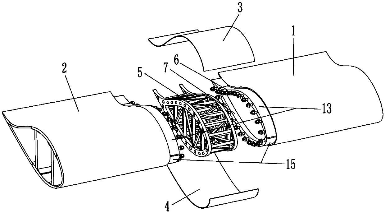
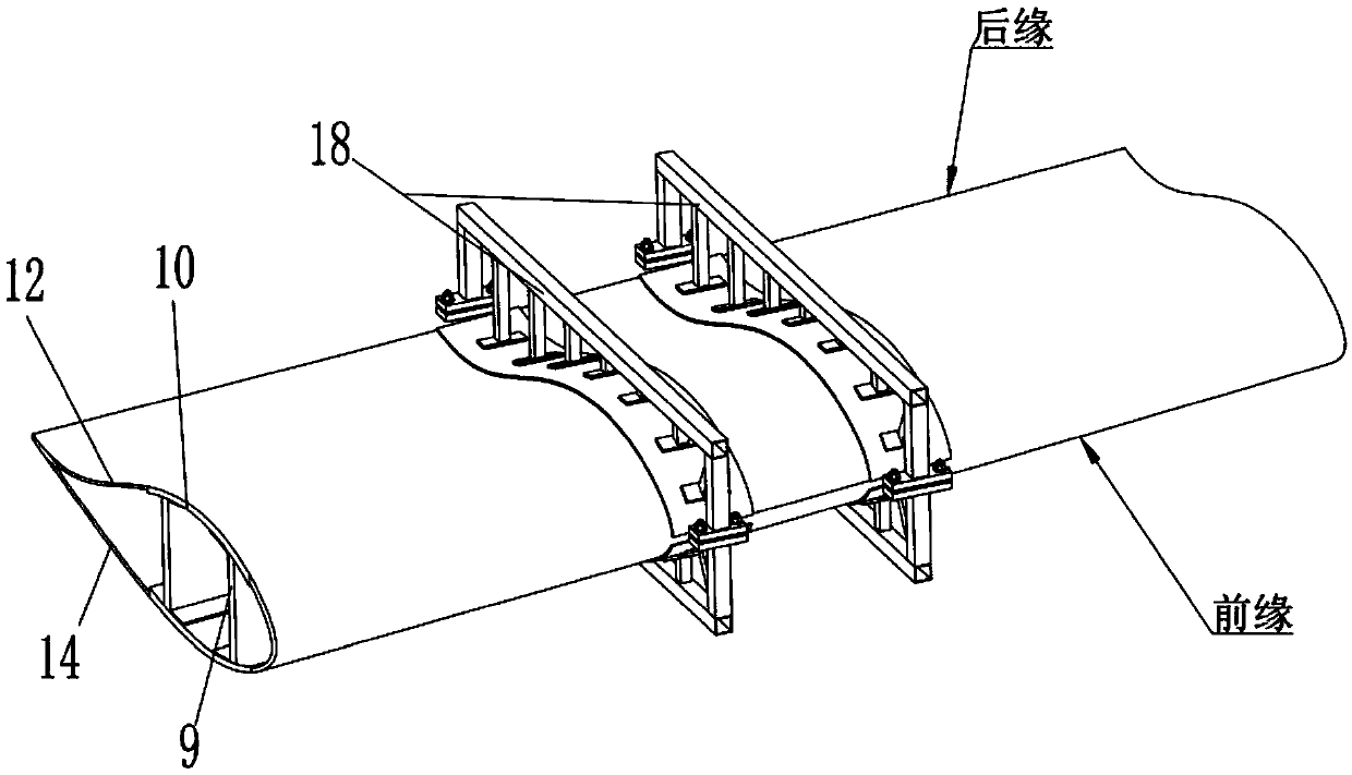
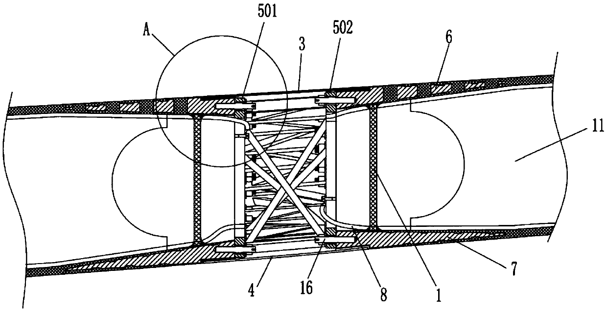
[0036] like Figure 1 to Figure 8As shown, the segmented combined wind turbine blade described in this embodiment includes a blade tip section 1, a blade root section 2, a first aerodynamic shape combination plate 3, a second aerodynamic shape combination plate 4, and a truss-type steel structure 5. The first insert 6, the second insert 7, the lightning protection wire 8, the blade tip section 1 and the blade root section 2 are built with a web 9 and a main beam 10, and an end face is made at a distance of 100 mm from the end face The baffle plate 11, the inside of the windward surface 12 of the blade tip section 1 and the blade root section 2 are attached and fixed with a first insert 6, the shape and size of the first insert 6 is matched with the inside of the windward surface 12, and exposed There is an adhesive surface 13 with a width of 100mm, which is used for pasting a...


PUM


Abstract

The invention discloses a segmented and combined type wind turbine generator blade and a manufacturing method thereof. The segmented and combined type wind turbine generator blade comprises a blade tip section, a blade root section, a first aerodynamic configuration composition board, a second aerodynamic configuration composition board, a truss type steel structure, a first inset and a second insert. The first insert is fixed to the inner sides of the windward sides of the blade tip section and the blade root section. A bonding face is exposed out of the first insert. The second insert is fixed to the inner sides of the lee sides of the blade tip section and the blade root section. A bonding face is exposed out of the second insert. First bolt holes are formed in the connection end face of the first insert and the second insert. Second bolt holes are formed in the flange faces at the two ends of the truss type steel structure. The truss type steel structure is connected with the first insert and the second insert through studs, and the truss type steel structure, the first insert and the second inset are fixed through self-locking nuts. The blade tip section and the blade root section are connected into a whole through the truss type steel structure. The first aerodynamic configuration composition board and the second aerodynamic configuration composition board are pasted on the corresponding bonding faces. Anti-thunder wires are arranged on the windward sides and the lee sides of the blade tip section and the blade root section respectively. By means of the segmented and combined type wind turbine generator blade and the manufacturing method, reliability of connection of the two sections and convenience of engineering on-site segmented connection are achieved.

Description

technical field [0001] The invention relates to the technical field of wind power generator blades, in particular to a segmented combined wind power generator blade and a manufacturing method thereof. Background technique [0002] With the demand of the market, the length of wind turbine blades is currently increasing, and the transportation cost and difficulty of transportation are also increasing. In order to solve these factors that restrict the development of long blades of wind turbines, major blade manufacturers have begun to work on segmented Development of blade technology. Figure 13 For a wind turbine blade, the blade is divided into two parts from near the middle. At present, there are two end faces at the segmented position of the blade, and metal flanges with drilling screw connection holes are embedded respectively, and the blade root part and the blade are connected by screws. Segmented blades with joined together tipped sections. This method can satisfy the ...

Claims


Application Information

Patent Timeline
IPC IPC(8): F03D1/06F03D80/30
CPCF03D1/0675F05B2240/302Y02E10/72Y02P70/50
Inventor 刘叶霖
Owner 河南明阳智慧能源有限公司
Features
  • R&D
  • Intellectual Property
  • Life Sciences
  • Materials
  • Tech Scout
  • Unparalleled Data Quality
  • Higher Quality Content
  • 60% Fewer Hallucinations
Learn More