Multi-cylinder rotary type compressor

A technology of rotary compressors and cylinders, used in rotary piston/oscillating piston pump components, elastic fluid rotary piston/oscillating piston pump combinations, and mechanical equipment, etc. Influence and affect the accuracy of the compression mechanism and the reduction of compression efficiency, etc., to avoid deformation, ensure the centering accuracy, and ensure the performance.

Inactive Publication Date: 2016-04-20
GUANGDONG MEIZHI COMPRESSOR +1
View PDF8 Cites 1 Cited by
  • Summary
  • Abstract
  • Description
  • Claims
  • Application Information

AI Technical Summary

Problems solved by technology

However, due to the above-mentioned notched edge, the deformation of the inner peripheral wall of the housing becomes polygonal, and this deformation affects the accuracy of the compression mechanism part fixed to the inner peripheral wall of the housing.
As a result, the compression efficiency will be reduced
Moreover, the deformation of the inner peripheral wall of the housing will affect the alignment accuracy of the stator of the motor and the rotor of the motor

Method used


Image

  • Multi-cylinder rotary type compressor
  • Multi-cylinder rotary type compressor
  • Multi-cylinder rotary type compressor

Examples


Embodiment 1

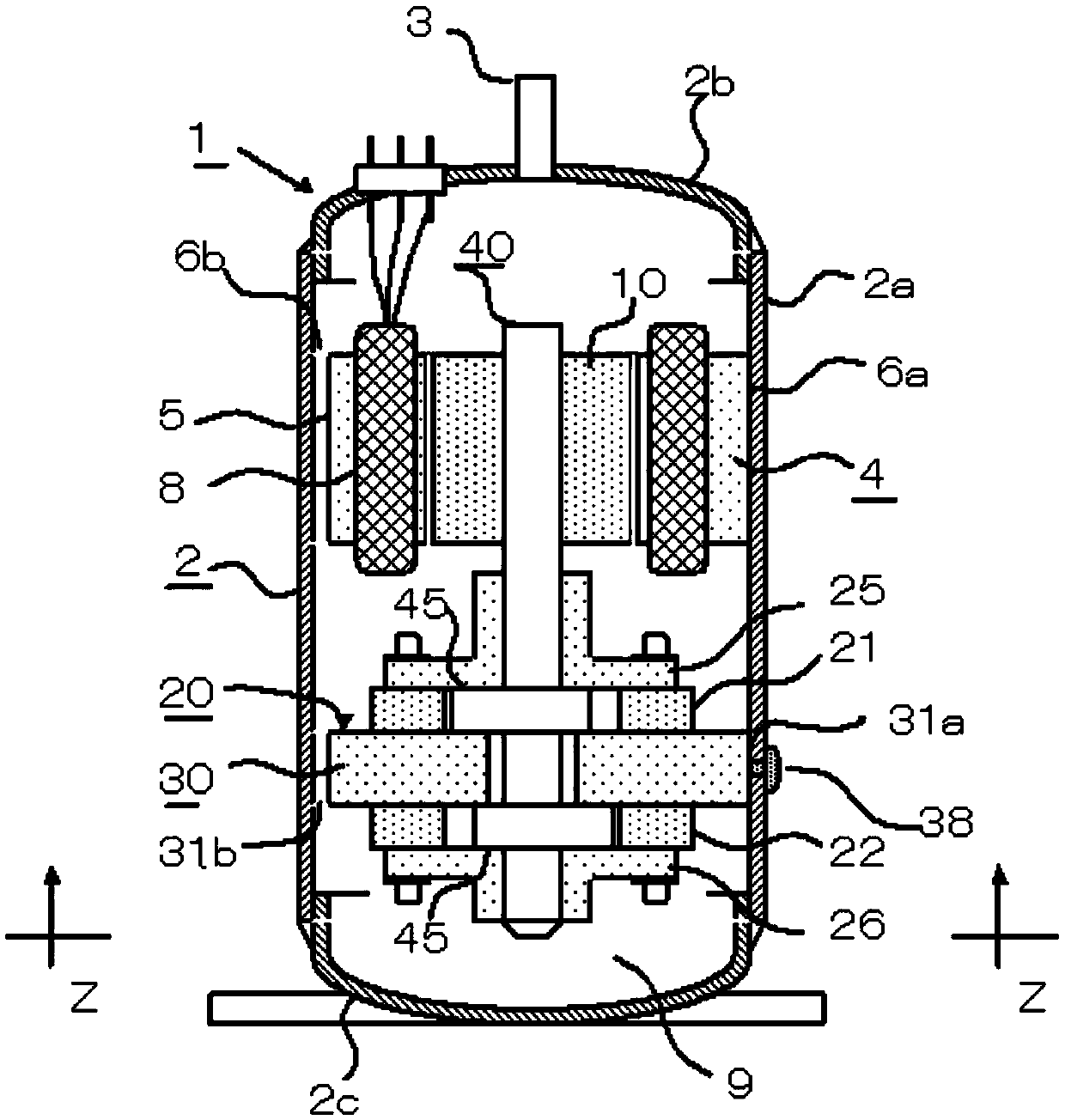
[0044] figure 1 The internal structure of the completed multi-cylinder rotary compressor 1 is shown. The sealed casing 2 is composed of a cylindrical casing 2a, a first end plate 2b and a second end plate 2c welded to the openings at both ends thereof, and the motor 4 and the compression mechanism part 20 are accommodated therein. In addition, the bottom of the sealed housing 2 has an oil storage chamber 9 .

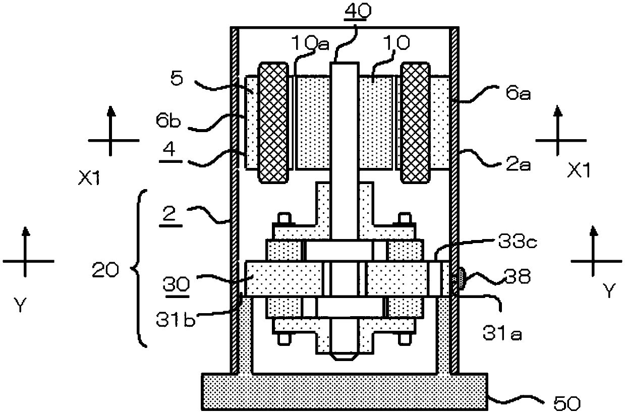
[0045] The motor 4 is composed of a stator 5 and a rotor 10, and the compression mechanism part 20 is composed of a cylinder 21 and a cylinder 22 provided with a compression chamber, a partition plate 30 provided between these cylinders, a crankshaft 40 that eccentrically drives a piston 45 housed in each cylinder, and the cylinder 21. The top of the crankshaft 40 and the bottom of the cylinder 22 are respectively combined with a main bearing 25 and an auxiliary bearing 26 for slidingly supporting the crankshaft 40, and a piston (not shown) that reciprocates synchronous...

Embodiment 2

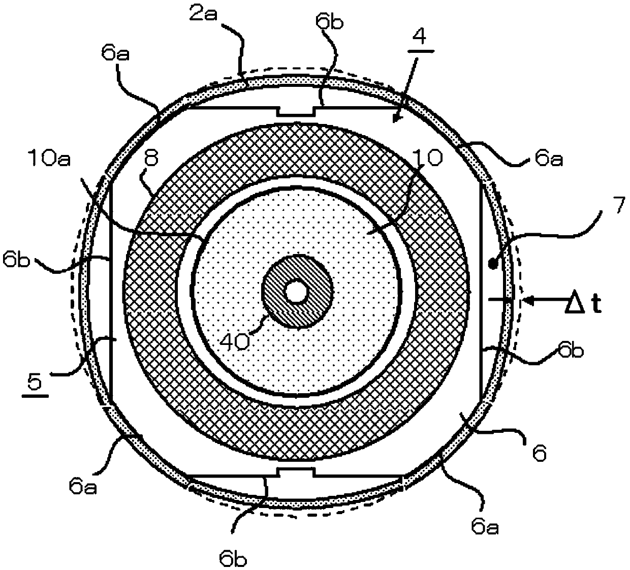
[0063] If there is a non-combined gap between the gap side 31b of the intermediate plate and the cylindrical housing 2a, the purpose can be achieved, so the shape of the gap side 31b does not need to be similar to the shape of the cutout side 6b of the stator core. Figure 5 The middle partition 32 shown in , according to the above considerations, the shape of the gap side 31b is set as a large arc. Therefore, the width of the outer peripheral gap 31c becomes small, and the rigidity of the partition plate 32 increases.

[0064] The buffer hole 33c added between the joint edge 31a and the grinding surface 33a prevents the deformation of the joint edge 31a in contact with the inner circumference of the cylindrical shell 2a from propagating to the grinding surface 33a, and is a means to prevent deformation of the cylinder fixed on the grinding surface 33a. In addition, the buffer hole 33c is also an oil hole that communicates with the inside of the sealed housing 2 and the oil st...

Embodiment 3

[0068] Figure 7 and Figure 8 Embodiment 3 shown in , relates to the welding of the outer periphery of the joining edge 31a of the intermediate partition 32 and the inner periphery of the cylindrical shell 2a. Figure 7 is equipped with Figure 5 A plan view of the compression mechanism part 20 of the shown intermediate partition plate 32 viewed from the side of the second end plate 2c, and figure 1 The Z-Z cross-sectional diagram is equivalent.

[0069] Figure 7 Among them, spot welding 38 is performed at the centers of the four joining sides 31a of the intermediate partition 32 combined with the inner periphery of the cylindrical shell 2a. As in this example, if the joint side 31a is welded by one spot welding, the joint side 31a may be shortened and the gap side 31b may be lengthened.

[0070] Figure 8 , The fixing strength of the compression mechanism part 20 can be further improved by performing two spot weldings 38 on the joint side 31 a having a sufficient arc ...


PUM


Abstract

The invention discloses a multi-cylinder rotary type compressor. The multi-cylinder rotary type compressor comprises a seal shell, a motor and a compressing mechanism portion, wherein the seal shell is composed of a cylindrical shell and end plates sealing the opening ends of the cylindrical shell; the motor is composed of a stator and a rotor; the space between two adjacent air cylinders of the compressing mechanism portion is provided with an intermediate partition plate; the outer circumferential wall of the stator is composed of multiple round edges which are connected with the inner circumferential wall of the cylindrical shell and multiple notch edges which are not connected with the inner circumferential wall of the cylindrical shell; the outer circumferential wall of the intermediate partition plate is composed of multiple jointing edges which are connected with the inner circumferential wall of the cylindrical shell and multiple gap edges which are not connected with the inner circumferential wall of the cylindrical shell; the multiple round edges and the multiple jointing edges are arranged in a one-to-one-correspondence mode in the axial direction of the cylindrical shell. According to the multi-cylinder rotary type compressor, deformation of the compressing mechanism portion can be avoided, centering adjustment precision of the stator and the rotor can be guaranteed, and therefore compression efficiency and motor performance are guaranteed.

Description

technical field [0001] The invention relates to the refrigeration field, in particular to a multi-cylinder rotary compressor. Background technique [0002] The inner peripheral wall of the cylindrical shell of the rotary compressor directly shrinks and fixes the outer peripheral wall of the motor stator with several notched sides, and this design is relatively common. However, due to the above-mentioned notched edge, the deformation of the inner peripheral wall of the housing becomes polygonal, and this deformation affects the accuracy of the compression mechanism portion fixed to the inner peripheral wall of the housing. As a result, compression efficiency decreases. Moreover, the deformation of the inner peripheral wall of the housing will affect the centering accuracy of the stator of the motor and the rotor of the motor. Contents of the invention [0003] The present invention aims to solve one of the technical problems in the related art at least to a certain extent...

Claims


Application Information

Patent Timeline
Patent Type & Authority Applications(China)
IPC IPC(8): F04C23/00F04C29/00
CPCF04C23/00F04C29/00
Inventor 小津政雄宋鹏杰王玲
Owner GUANGDONG MEIZHI COMPRESSOR
Why Eureka
Try Eureka