Supercharge Your Innovation With Domain-Expert AI Agents!

High-temperature temperature measurement element device with adjustable measuring point positions

A technology of measuring point position and temperature measuring element, which is applied in the field of high temperature temperature measuring element device, can solve the problems of high price of temperature sensing material, affecting engine performance, increasing flow channel blockage ratio, etc., and achieves major social and economic benefits, The effect of reducing impact and reducing measurement costs

Inactive Publication Date: 2016-04-20
SHENYANG LIMING AERO-ENGINE GROUP CORPORATION
View PDF6 Cites 3 Cited by
  • Summary
  • Abstract
  • Description
  • Claims
  • Application Information

AI Technical Summary

Problems solved by technology

In addition, since the traditional temperature measuring element can only achieve fixed position measurement, multiple temperature measuring elements need to be inserted when measuring the temperature field. When the space of the measured flow field is limited, multi-point measurement will increase the blockage ratio of the flow channel and even affect the engine. Performance, and the price of temperature-sensing materials for high-temperature testing is relatively high, and multi-point measurement will also increase the measurement cost

Method used


Image

  • High-temperature temperature measurement element device with adjustable measuring point positions
  • High-temperature temperature measurement element device with adjustable measuring point positions
  • High-temperature temperature measurement element device with adjustable measuring point positions

Examples


Embodiment Construction

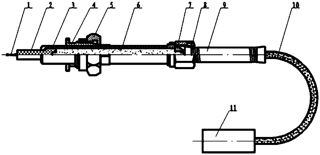
[0021] Such as figure 1 Shown is a high temperature temperature measuring element device that can adjust the position of the measuring point. The device includes a thermocouple 1, a corundum porcelain tube 2, a housing 3, a mounting seat 4, a mounting seat nut 5, hot cement 6, and a fixing clip 7 , fixed clip nut 8, spring tube 9, glass wool casing 10 and aviation electrical connector 11;

[0022] The thermocouple 1 is plugged into the corundum porcelain tube 2, and the corundum porcelain tube 2 equipped with the thermocouple 1 is inserted from one end of the housing 3;

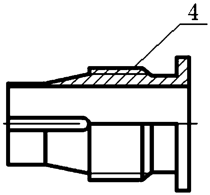
[0023] The other end of the housing 3 is provided with an external thread, and the housing 3 equipped with the thermocouple 1 and the corundum porcelain tube 2 is plugged into the mounting seat 4, and the mounting base 4 is fixed on the housing 3 by installing the nut 5 superior;

[0024] The housing 3 is filled with hot cement 6;

[0025] The part of the thermocouple 1 beyond the housing 3 is penetrated i...


PUM


Abstract

The invention discloses a high-temperature temperature measurement element device with adjustable measuring point positions. The device comprises a thermocouple, a corundum porcelain tube, a housing, a mounting base, a mounting base cap nut, hot cement, a fixing clamp, a fixing clamp cap nut, a spring tube, a fiberglass casing pipe, and a aviation electric connector. The thermocouple is connected with the corundum porcelain tube in an inserted mode. The corundum porcelain tube which is equipped with the thermocouple is inserted in the housing from one end of the housing. The other end of the housing is provided with outer screw threads. The housing is inserted in the mounting base. The mounting base is fixed on the housing through the mounting base cap nut. The housing is filled up with hot cement. The part, protruding from the housing, of the thermocouple is stuck into the fiberglass casing pipe. The fixing clamp is stuck in the fiberglass casing pipe and to the tail end of the housing. The spring tube is stuck in the fiberglass casing pipe and to the end of the fixing clamp. The fixing clamp cap nut sleeves the fixing clamp and is screwed and fixed to one end of the housing. The tail part of the thermocouple in the fiberglass casing pipe and the aviation electric connector are welded together. The advantages of the high temperature measurement element device are: the manufacture of the technical scheme is simple; the design of the structure is reasonable; the operability is high.

Description

technical field [0001] The invention relates to the technical field of aero-engine performance testing, in particular to a high-temperature temperature-measuring element device capable of adjusting the position of a measuring point. Background technique [0002] Temperature is an important parameter in the working process of an aeroengine, especially the measurement of the gas temperature field at the outlet of the combustion chamber is of great significance for evaluating the efficiency of the combustion chamber, determining the life of the rotor blades, and determining whether the guide blades are ablated. With the improvement of thrust-to-weight ratio performance of the engine, the outlet temperature of the combustion chamber is getting higher and higher (greater than 1000°C), and the protective shell of the common temperature measuring element is easily ablated, and the temperature cannot be directly measured. Field temperature data are generally obtained by calculation....

Claims


Application Information

Patent Timeline
IPC IPC(8): G01K7/02G01K1/14
CPCG01K7/02
Inventor 吴颖赵宇阴松凯田金光张荫鳌
Owner SHENYANG LIMING AERO-ENGINE GROUP CORPORATION
Features
  • R&D
  • Intellectual Property
  • Life Sciences
  • Materials
  • Tech Scout
  • Unparalleled Data Quality
  • Higher Quality Content
  • 60% Fewer Hallucinations
Learn More