Electric leakage detection equipment and detection method thereof

A leakage detection and equipment technology, applied in the field of power systems, can solve the problems of reducing the accuracy of leakage fault ports, inaccurate second leakage current detection results, and large overall volume of leakage detection equipment, achieving high power conversion efficiency and overall volume Small, accuracy-enhancing effect

Active Publication Date: 2016-04-20
HUAWEI DIGITAL POWER TECH CO LTD
View PDF8 Cites 9 Cited by
  • Summary
  • Abstract
  • Description
  • Claims
  • Application Information

AI Technical Summary

Problems solved by technology

[0006] 1. Since the leakage detection device includes not only the first power changing circuit but also the second power conversion circuit, and there is a certain distance limitation between the contacts in the relay, the overall volume of the leakage detection device is relatively large
2. The test voltage output by the second power conversion circuit is only used for the detection of the second leakage current, and does not supply power to the remote equipment, which reduces the conversion efficiency of the external power supply
3. In order to improve the conversion efficiency of the external power supply, the test voltage cannot be set too high, and when the test voltage is small, it may not be able to break through the line insulation layer at the leakage fault port, resulting in inaccurate detection results of the second leakage current, thereby reducing In order to determine the accuracy of the leakage fault port

Method used


Image

  • Electric leakage detection equipment and detection method thereof
  • Electric leakage detection equipment and detection method thereof
  • Electric leakage detection equipment and detection method thereof

Examples


Embodiment Construction

[0095] In order to make the object, technical solution and advantages of the present invention clearer, the implementation manner of the present invention will be further described in detail below in conjunction with the accompanying drawings.

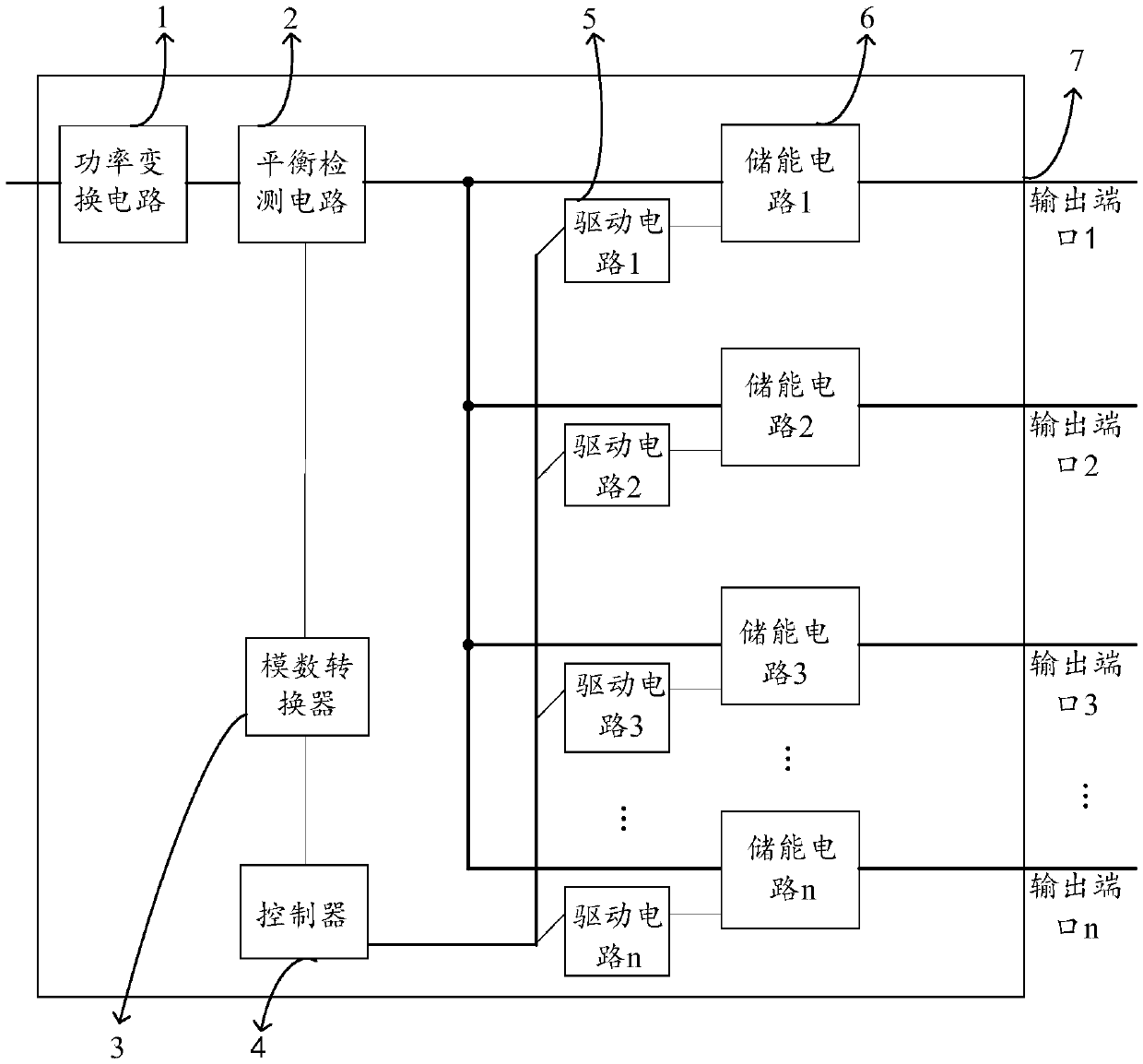
[0096] figure 2 It is a schematic structural diagram of a leakage detection device provided by an embodiment of the present invention, see figure 2 , the device includes: a power conversion circuit 1, a balance detection circuit 2, an analog-to-digital converter 3, a controller 4, N drive circuits 5, N energy storage circuits 6 and N pairs of output ports 7, and the N drive circuits 5. The N energy storage circuits 6 are in one-to-one correspondence with the N pairs of output ports 7, and the N is greater than or equal to 1;

[0097] The input end of the power conversion circuit 1 is connected to the external power supply, the output end of the power conversion circuit 1 is connected to the first end of the balance detection circuit...


PUM


Abstract

The invention discloses electric leakage detection equipment and a detection method thereof, which belong to the field of power systems. The electric leakage detection equipment comprises a power conversion circuit, a balance detection circuit, an analog-to-digital converter, a controller, N driving circuits, N energy storage circuits and N pairs of output ports, wherein the N driving circuits, the N energy storage circuits and the N pairs of output ports are in one-to-one correspondence, and the N is greater than or equal to 1; an output end of the power conversion circuit is connected with the balance detection circuit, and the balance detection circuit is connected with an input end of the analog-to-digital converter and first input ends of the N energy storage circuits; an output end of the analog-to-digital converter is connected with an input end of the controller, an output end of the controller is connected with input ends of the N driving circuits, and output ends of the N driving circuits are connected with second input ends of the N energy storage circuits in a corresponding manner. The electric leakage detection equipment performs electric leakage detection directly by means of an operating voltage, is small in overall size and high in power conversion efficiency, and can increase accuracy of determining an electric leakage fault port.

Description

technical field [0001] The invention relates to the field of power systems, in particular to a leakage detection device and a detection method thereof. Background technique [0002] The remote power supply system includes the local end system and the remote system. When the remote power supply system supplies power to the remote equipment, the local end system can raise the external power supply of 48 DC voltage (English: Voltage Direct Current, referred to as: VDC) to 380VDC high voltage, And the 380VDC high voltage is transmitted to the remote system, and the remote system converts the 380VDC high voltage to 48VDC to supply power to the remote equipment. When the local end system is running, in order to lead out unsafe currents such as residual electricity and induced electricity on the line, a grounding wire will be set up, and the unsafe current will flow into the ground through the grounding wire. These currents flowing into the ground are called leakage current. Beca...

Claims


Application Information

Patent Timeline
Patent Type & Authority Applications(China)
IPC IPC(8): G01R31/02
CPCG01R31/50
Inventor 樊孝斌李红勇丁晓武
Owner HUAWEI DIGITAL POWER TECH CO LTD
Why Eureka
Try Eureka