Actual measurement sound velocity-based ultrasonic distance measuring method and ultrasonic sensor

A distance measurement method, ultrasonic technology, applied in the direction of sound wave re-radiation, radio wave measurement system, instrument, etc., can solve the problems of unstable measurement and large measurement deviation, and achieve the effect of stable data and reduced interference

Inactive Publication Date: 2016-04-20
湖南沄辉科技股份有限公司
View PDF5 Cites 11 Cited by
  • Summary
  • Abstract
  • Description
  • Claims
  • Application Information

AI Technical Summary

Problems solved by technology

[0011] Although the ultrasonic liquid level measurement system disclosed in this reference document adopts the metal tube compensation method, in the actual measurement, the temperature measurement sound velocity is used as the standard, and the metal tube is used as the offset

Method used


Image

  • Actual measurement sound velocity-based ultrasonic distance measuring method and ultrasonic sensor
  • Actual measurement sound velocity-based ultrasonic distance measuring method and ultrasonic sensor
  • Actual measurement sound velocity-based ultrasonic distance measuring method and ultrasonic sensor

Examples


Embodiment 1

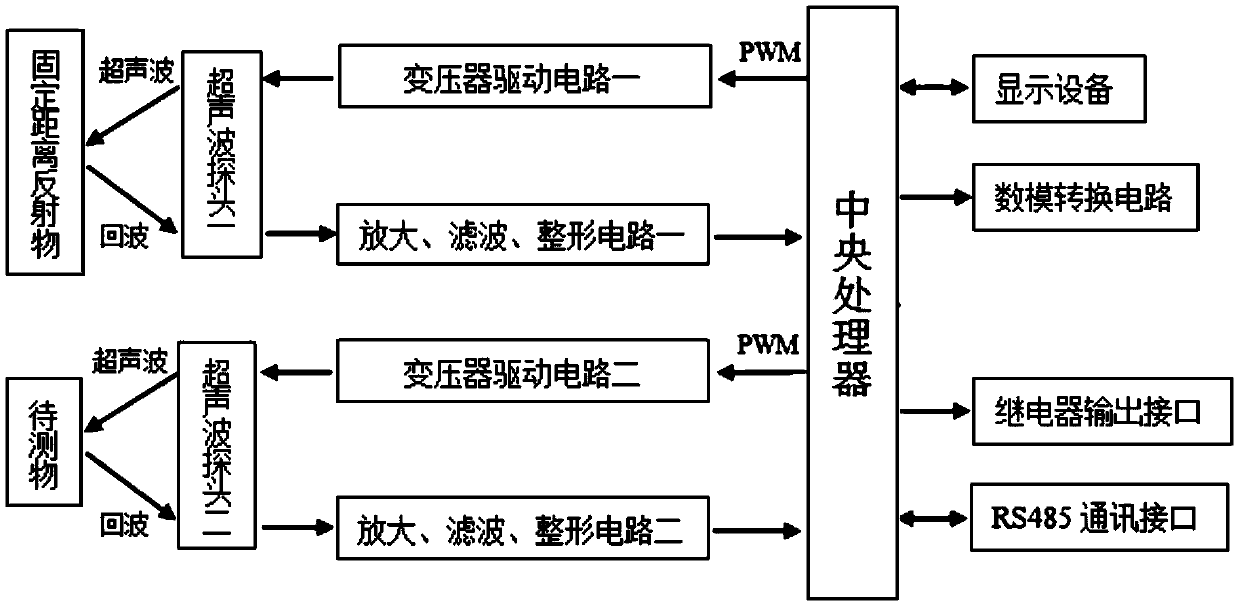
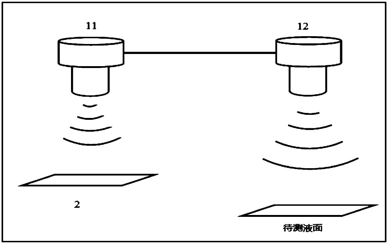
[0077] Such as figure 1 , figure 2 Shown:

[0078] An ultrasonic liquid level transmitter comprises an ultrasonic probe one (velocity measuring probe) 11 and an ultrasonic probe two 12 (distance measuring probe); the ultrasonic probe one 11 is used to measure the actual sound velocity; the ultrasonic probe two 12 is used for measuring the liquid level to be measured distance.

[0079] The central processing unit is respectively connected to the transformer driving circuit one and the amplification, filtering and shaping circuit one, and the central processing unit sends a PWM signal through the transformer driving circuit one to drive the ultrasonic probe one 11 to emit ultrasonic waves, and the ultrasonic waves meet a reflector arranged at a known fixed distance 2 (the reflector can be a baffle) and emit back, the reflected ultrasonic echo is received by the ultrasonic probe-11, and converted into an ultrasonic echo signal, which is amplified and filtered 1. After being p...

Embodiment 2

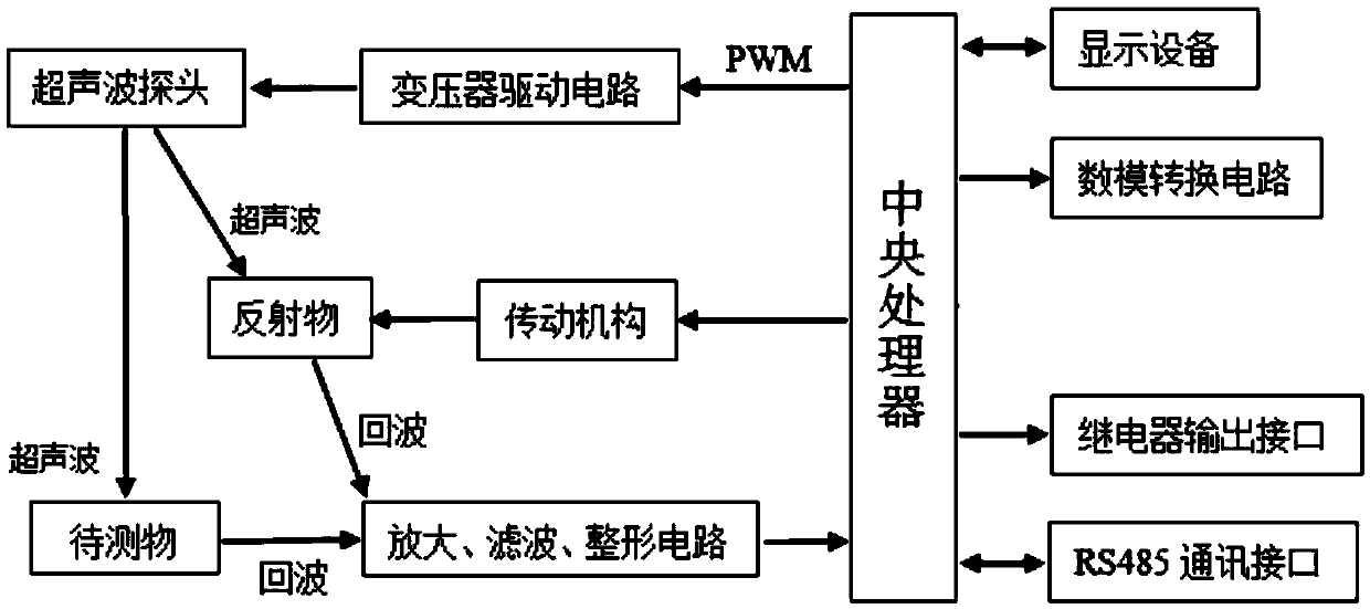
[0103] Such as image 3 , Figure 4 Shown:

[0104] An ultrasonic liquid level transmitter comprises an ultrasonic probe 1' and a central processing unit:

[0105] The central processing unit is connected with a transmission mechanism 3', and the transmission mechanism 3' is connected with a reflector 2' (the reflector can be a baffle);

[0106] The transmission mechanism 3' is used to move the reflector 2' connected to the transmission mechanism 3' directly under the ultrasonic probe 1' after receiving the drive signal sent by the central processing unit, so as to measure the actual speed of sound; the transmission mechanism 3' is also used to receive the retraction signal sent by the central processor after measuring the actual speed of sound, and move the projectile 2' out of the measurement range of the ultrasonic probe;

[0107] The central processing unit is connected to the transformer driving circuit and the amplification, filtering and shaping circuits, and the ult...


PUM


Abstract

The invention relates to an actual measurement sound velocity-based ultrasonic distance measuring method and an ultrasonic sensor. The method includes the following steps that: A, a known fixed distance is set, and an ultrasonic probe is utilized to detect actual sound velocity of a current time; and B, distance measurement of an object to be measured is performed through utilizing the actual sound velocity obtained in the step A. According to the actual measurement sound velocity-based ultrasonic distance measuring method of the invention, a traditional method in which measured temperature is utilized to compensate sound velocity is discarded, while sound velocity is directly measured; the actual sound velocity of a current environment is measured, and then, the distance of the object to be measured is measured based on the actual sound velocity, and therefore, the error and instability of measurement accuracy which are caused by the influences of temperature, pressure and humidity in the air, air quality and the like in a measurement process can be avoided. The invention also relates to an ultrasonic sensor adopting the above method.

Description

technical field [0001] The present invention relates to an ultrasonic ranging method based on measured sound velocity and an ultrasonic sensor, in particular to an ultrasonic ranging method based on measured sound velocity and an ultrasonic sensor with high stability and high precision, which can make ultrasonic measurement free from external influences. It belongs to the technical field of ultrasonic measurement. Background technique [0002] As a non-contact sensor, the ultrasonic sensor has the advantages of convenient installation, high stability, and no medium pollution. It can be widely used in various liquid level measurement occasions such as industry and agriculture, especially in toxic and polluted occasions. Therefore, ultrasonic sensors have incomparable advantages over other types of ranging sensors. However, because ultrasonic measurement is easily affected by the external environment, the compensation method is not perfect, resulting in low measurement repeat...

Claims


Application Information

Patent Timeline
IPC IPC(8): G01S15/08G01F23/296
CPCG01S15/08G01F23/296
Inventor 周自平杨席瑛健罗奎冯健
Owner 湖南沄辉科技股份有限公司
Why Eureka
Try Eureka