
A Modeling Method Suitable for Numerical Wind Tunnel Simulation of Mountain Buildings
A modeling method and numerical wind tunnel technology, applied in 3D modeling, image data processing, electrical digital data processing, etc., can solve problems such as wind field influence, narrow application range, complex modeling, etc., to achieve simple modeling, Improved accuracy and wide application range
- Summary
- Abstract
- Description
- Claims
- Application Information
AI Technical Summary
Problems solved by technology
Method used
Image

Examples
Embodiment Construction
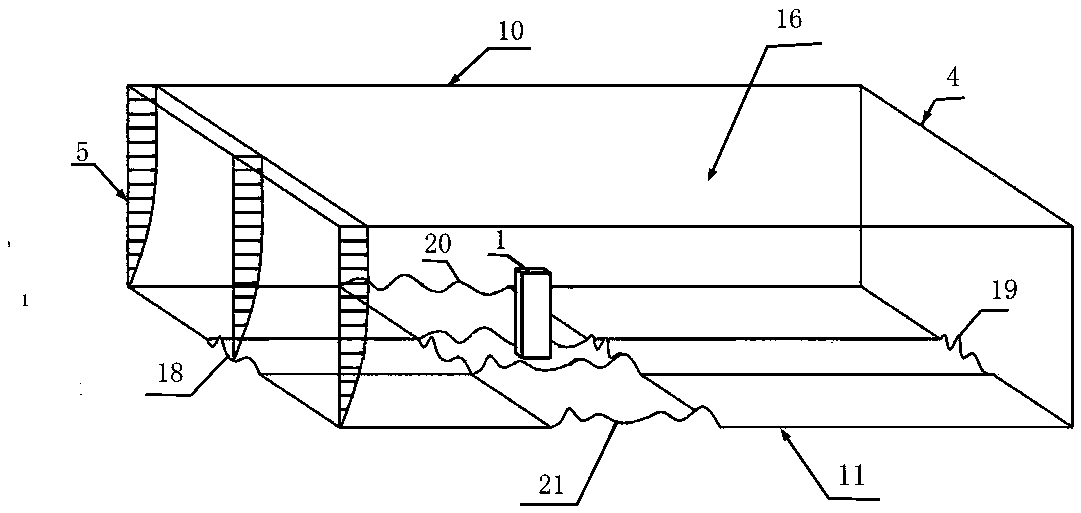
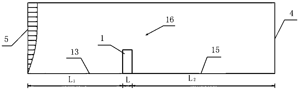
[0041] Examples see Figure 1-5 , a modeling method suitable for numerical wind tunnel simulation of mountainous buildings, the steps are as follows:
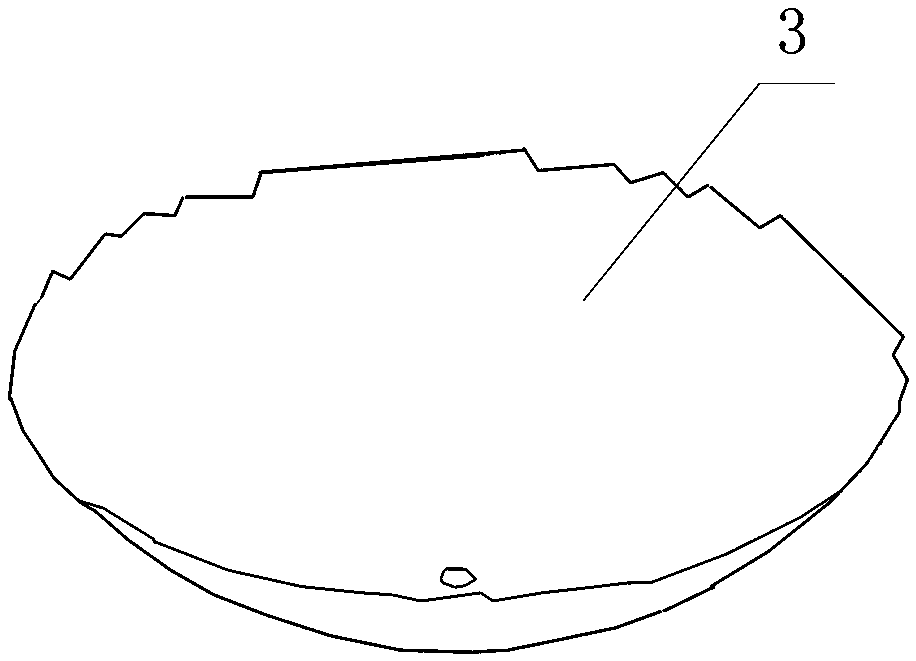
[0042] Step 1: If image 3 As shown, according to the building size and coordinate data in the actual construction plan, the CAD software is used to draw a picture, and the test building model is established, that is, the FAST reflective panel 3. The size of the FAST reflective panel 3 is equal to the size of the FAST reflective panel in the actual construction plan;
[0043] Step 2: If Figure 4 As shown, according to the measured terrain coordinate data, a mountain model 2 is established in the CAD drawing, wherein the mountain model 2 is obtained by fitting according to the measured terrain coordinate data;
[0044] Step 3: Determine the vertical distance L from the FAST reflection panel 3 to the entrance 5 of the wind field calculation domain 1 And the vertical distance L between the FAST reflection panel 3 and the outle...
PUM
 Abstract
Description
Claims
Application Information