
Method for using laser radar scanning method to calibrate dynamic pedestrians and vehicles in video in snowing or raining state

A technology in lidar and video, applied in image data processing, instrument, character and pattern recognition, etc., can solve the problems of inaccurate recognition of dynamic objects and poor real-time performance.

Active Publication Date: 2016-04-20
HARBIN INST OF TECH
View PDF4 Cites 8 Cited by
  • Summary
  • Abstract
  • Description
  • Claims
  • Application Information

AI Technical Summary

Problems solved by technology

[0006] The purpose of the present invention is to solve the problem of poor real-time performance of the optical flow algorithm combined with the GMM speed classification algorithm and the inaccurate identification of dynamic objects, and proposes a method of using the laser radar scanning method to calibrate the dynamic pedestrians and vehicles in the video under the rain and snow state

Method used


Image

  • Method for using laser radar scanning method to calibrate dynamic pedestrians and vehicles in video in snowing or raining state
  • Method for using laser radar scanning method to calibrate dynamic pedestrians and vehicles in video in snowing or raining state
  • Method for using laser radar scanning method to calibrate dynamic pedestrians and vehicles in video in snowing or raining state

Examples


specific Embodiment approach 1

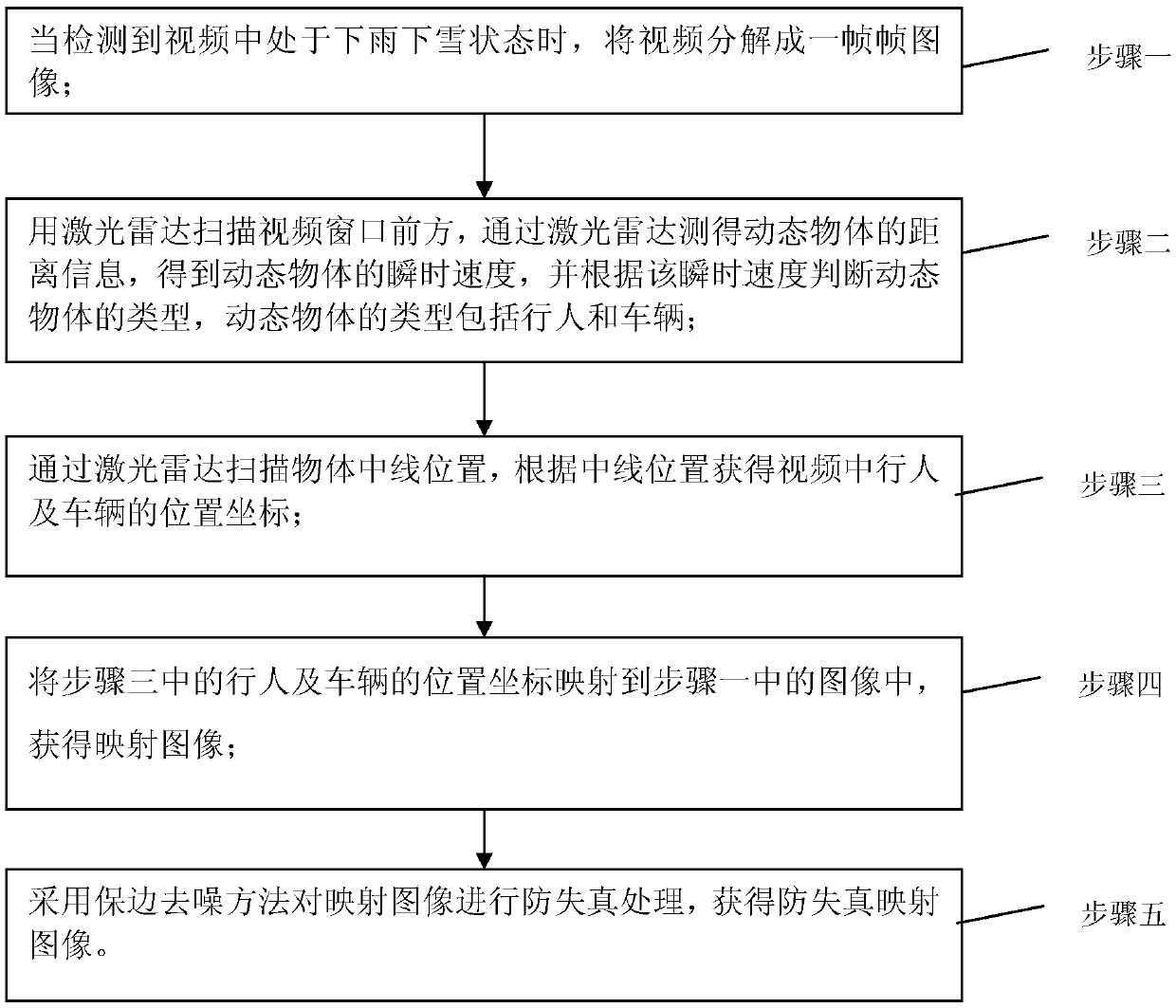
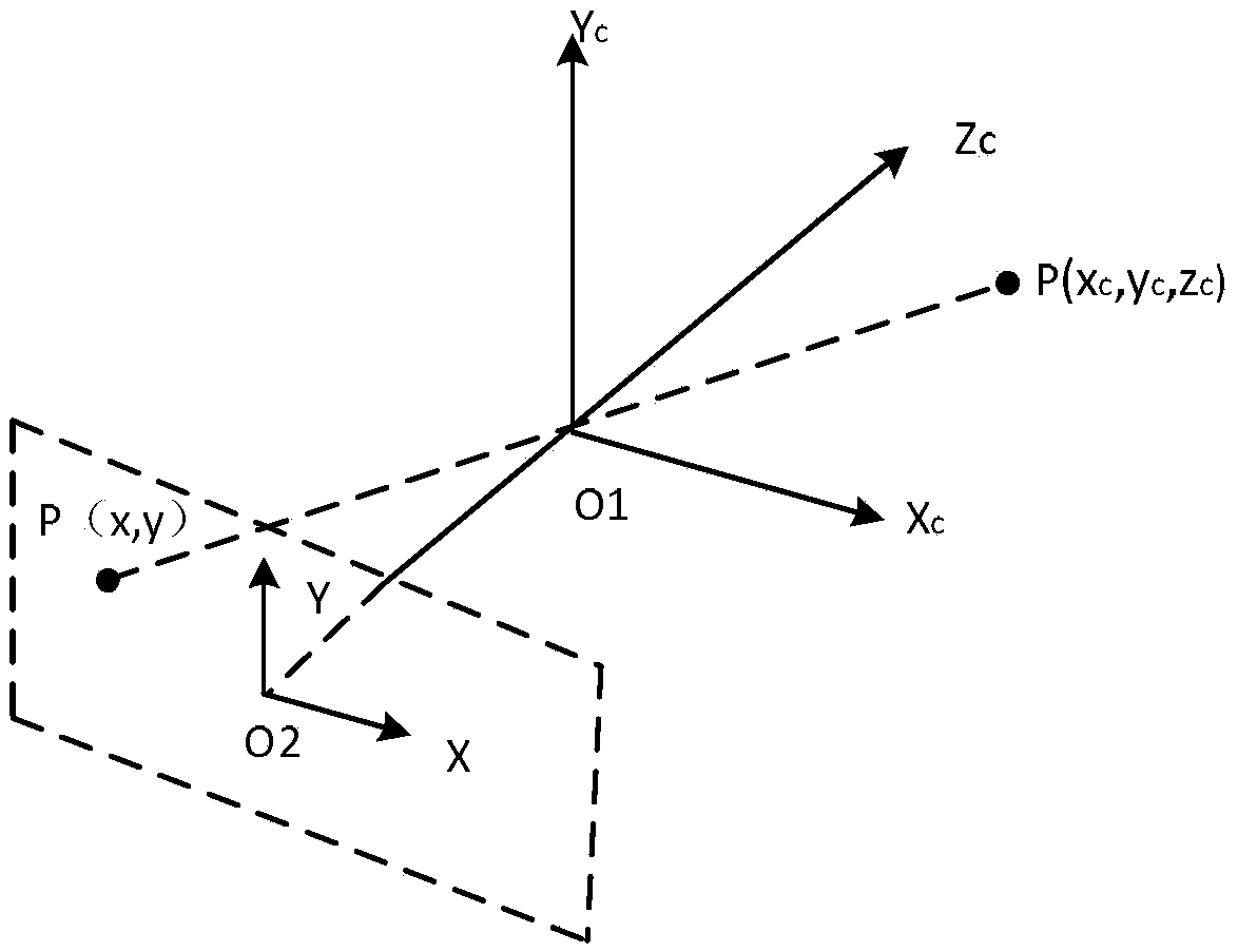
[0071] Specific implementation mode 1, refer to Figure 1 to Figure 7 This embodiment is described in detail. The method described in this embodiment uses the laser radar scanning method to calibrate the dynamic pedestrians and vehicles in the video under the rain and snow state. The pre-processing of the image before rain and snow removal;

[0072] The method comprises the steps of:

[0073] Step 1. When it is detected that the video is in a rainy or snowy state, the video is decomposed into frame-by-frame images;

[0074] Step 2. Scan the front of the video window with laser radar, measure the distance information of the dynamic object through the laser radar, obtain the instantaneous speed of the dynamic object, and judge the type of the dynamic object according to the instantaneous speed. The types of dynamic objects include pedestrians and vehicles;

[0075] Step 3. Scan the centerline position of the object through the laser radar, and obtain the position coordinates o...

specific Embodiment approach 2

[0080] Specific Embodiment 2. This embodiment is a further description of the method of using the laser radar scanning method to calibrate the dynamic pedestrians and vehicles in the video in the rain and snow state described in the first embodiment. In this embodiment,

[0081] In step 2, the laser radar is used to scan the front of the video window, and the distance information of the dynamic object measured by the laser radar is used to obtain the instantaneous speed of the dynamic object, and the type of the dynamic object is judged according to the instantaneous speed. The types of dynamic objects include pedestrians and vehicles. The specific process is as follows:

[0082] Set the speed threshold d, where d is 3km / h~5km / h;

[0083] If V>d, the dynamic object is a vehicle;

[0084] If 0<V<d, the dynamic object is a pedestrian.

specific Embodiment approach 3

[0085] Specific Embodiment 3. This embodiment is a further description of the method described in Embodiment 1, which adopts the laser radar scanning method to calibrate the dynamic pedestrians and vehicles in the video in the rain and snow state. In this embodiment,

[0086] In step 3, the centerline position of the object is scanned by the laser radar, and the position coordinates of pedestrians and vehicles in the video are obtained according to the centerline position. The specific process is as follows:

[0087] Step 31. Set the scanning height H of the lidar to 0.85m-1m, and the height is at the horizontal midline of the height of pedestrians and vehicles;

[0088] Step 32: The lidar scans horizontally to obtain the two-dimensional starting coordinates (X1, H) and end point coordinates (X2, H) at the horizontal midline of the dynamic object;

[0089] Step 33, according to the centerline principle, the height of pedestrians and vehicles is 2H;

[0090] Step three and fou...


PUM


Abstract

The invention relates to a method for using a laser radar scanning method to calibrate dynamic pedestrians and vehicles in a video in a snowing or raining state, relates to the field of image pattern recognition and machine intelligence, and solves the problem that an existing algorism is poor in real-time performance and inaccurate in recognition of dynamic objects. When a raining or snowing state is detected in a video, the video is decomposed into frames of images; a laser radar is utilized to scan the front of a video window, distance information of dynamic objects is measured through the laser radar, instantaneous speed of the dynamic objects is obtained, the types of the dynamic objects are judged according to the instantaneous speed, and the types of the dynamic objects include pedestrians and vehicles; center line positions of the objects are scanned through the laser radar, and position coordinates of the pedestrians and vehicles in the video are obtained according to the center line positions; the position coordinates of the pedestrians and vehicles in the Step 3 are mapped to the images in the Step 1, thereby obtaining mapping images; and an edge-preserving denoising method is adopted to perform distortion-preventing processing on the mapping images, thereby obtaining distortion-preventing mapping images. The method provided by the invention is suitable for detecting pedestrians and vehicles.

Description

technical field [0001] The invention relates to the fields of image pattern recognition and machine intelligence. Background technique [0002] In today's video rain and snow removal algorithm, the first thing is to detect that the video is in the state of rain and snow, and the optical flow algorithm is usually used to detect the state of the weather at this time. The basic principle of the optical flow method to detect moving objects is: to assign a velocity vector to each pixel in the image, which forms an image sports field. At a specific moment of movement, the points on the image and the points on the three-dimensional object One-to-one correspondence, this correspondence can be obtained from the projection relationship, and the image can be dynamically analyzed according to the velocity vector characteristics of each pixel. If there is no moving object in the image, the optical flow vector changes continuously throughout the image area. When there is a moving object...

Claims


Application Information

Patent Timeline
IPC IPC(8): G06K9/00G06T5/00
CPCG06T2207/10044G06T2207/10016G06T2207/20182G06T2207/20192G06T2207/30196G06V20/40G06V2201/08G06V2201/07G06T5/70
Inventor 王进祥王瑶付方发石金进徐伟哲蔡祎炜狄威王宇哲
Owner HARBIN INST OF TECH
Learn More