Small coplanar waveguide fed broadband antenna

A coplanar waveguide, broadband antenna technology, applied in the antenna grounding device, antenna grounding switch structure connection, radiating element structure and other directions, can solve serious problems that affect communication quality, antenna interference, etc., to reduce low frequency, impedance matching degree Good, reduced antenna size effect

Inactive Publication Date: 2016-04-20
TIANJIN UNIV
View PDF4 Cites 7 Cited by
  • Summary
  • Abstract
  • Description
  • Claims
  • Application Information

AI Technical Summary

Problems solved by technology

Moreover, if multiple antennas are arranged in a small space, the interference between the antennas will be serious,

Method used


Image

  • Small coplanar waveguide fed broadband antenna
  • Small coplanar waveguide fed broadband antenna
  • Small coplanar waveguide fed broadband antenna

Examples


Embodiment Construction

[0024] Below in conjunction with accompanying drawing, the present invention will be further described:

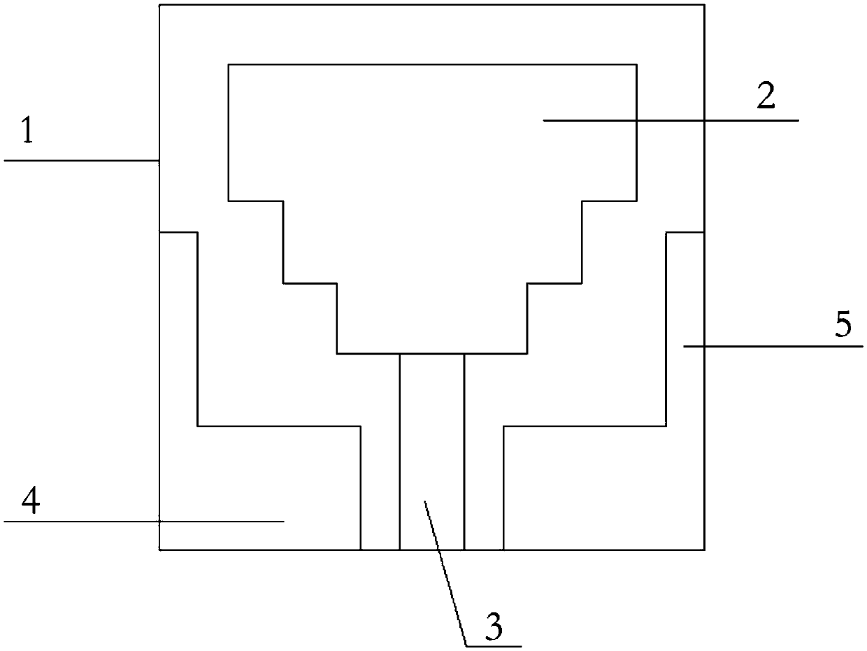
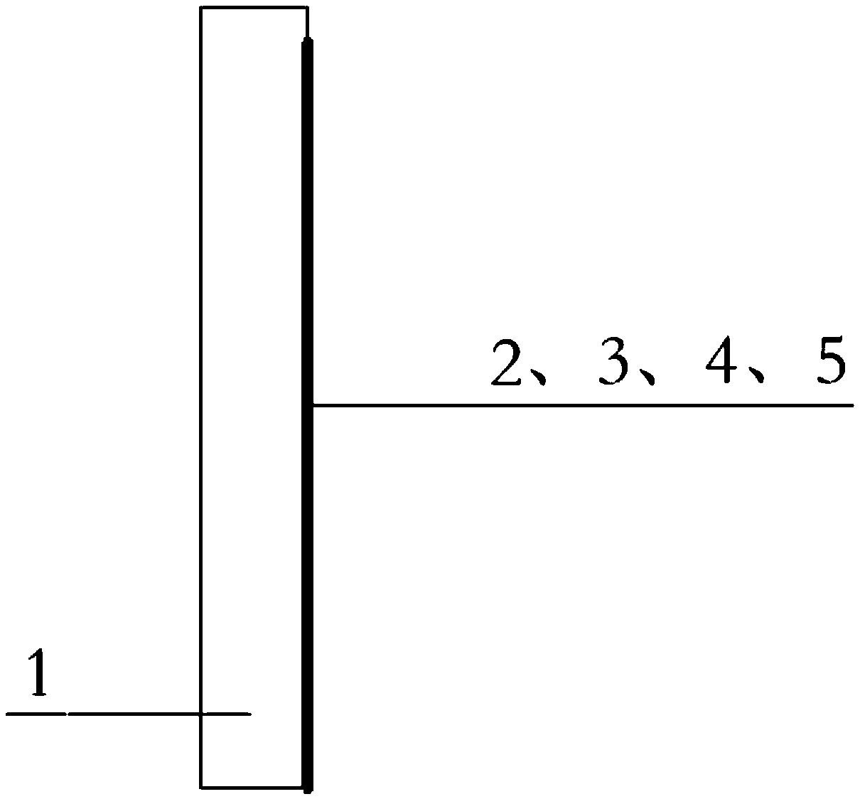
[0025] Such as figure 1 and figure 2 As shown, a small coplanar waveguide-fed broadband antenna includes a dielectric substrate 1 with a rectangular structure. The dielectric substrate 1 is made of epoxy resin (FR4Epoxy), its relative permittivity is 4.4, and its dielectric loss tangent The value is 0.02.

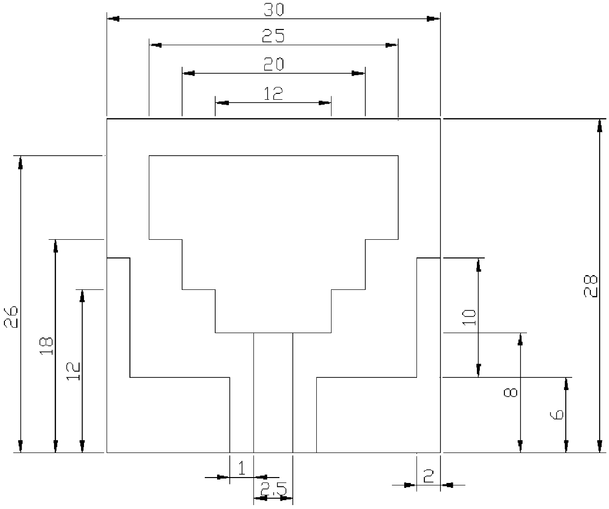
[0026] The antenna in this embodiment is fabricated on a dielectric substrate 1 with a size of 30mm×28mm by etching method. The thickness of the dielectric substrate 1 is 1.6mm. On one side of the substrate 1, the left and right sides of the radiation patch 2 are symmetrically etched with a three-level ladder structure integrated with the radiation patch. The lower end of the radiation patch 2 is connected to the feed network 3, and the feed The length of the network 3 is 8mm, the feeding method adopts coplanar waveguide feeding, the input impedance is 50Ω, the grou...


PUM

PropertyMeasurementUnit
Thicknessaaaaaaaaaa
Lengthaaaaaaaaaa
Lengthaaaaaaaaaa

Abstract

The invention discloses a small coplanar waveguide fed broadband antenna which comprises a dielectric substrate of rectangular structure, wherein the dielectric substrate is 1.6mm thick, a radiation patch, a feed network and earth plates are arranged on one side of the dielectric substrate respectively, three-level staircase structures integrated with the radiation patch are symmetrically disposed on the left and right sides of the radiation patch, the lower end of the radiation patch is connected with the feed network, the earth plate are symmetrically disposed on the left and right sides of the feed network, and a tuning stub which is integrated with the earth plate is arranged on the earth plate in a corresponding mode. The working band of the small coplanar waveguide fed broadband antenna covers 8.6 to 12.1 GHz, and the broadband antenna achieves good impedance matching within effective bandwidths. In addition, the broadband antenna is simple in structure, small in size, easy to produce, suitable for wireless communication systems, and wide in application prospect.

Description

technical field [0001] The invention relates to a broadband antenna, more specifically, to a small broadband antenna fed by a coplanar waveguide. Background technique [0002] Broadband antennas are proposed and developed mainly to compensate for the narrow bandwidth of narrowband antennas (such as microstrip antennas), and their important characteristics are broadband and large-scale coverage. In the wireless communication system, in order to realize the integration with other communication devices and enable the antenna to work in multiple situations at the same time, the miniaturization and broadband of the antenna have become a research hotspot. Moreover, if multiple antennas are arranged in a small space, the interference between the antennas will be serious, which will affect the communication quality, which also requires the antenna to have a wider working frequency band. [0003] At present, the design and application of broadband antennas have become one of the foc...

Claims


Application Information

Patent Timeline
IPC IPC(8): H01Q1/38H01Q1/48H01Q1/50
CPCH01Q1/38H01Q1/48H01Q1/50
Inventor 金杰张强李茜
Owner TIANJIN UNIV
Why Eureka
Try Eureka