Ultrasonic method and apparatus for characterizing the propagation of ultrasonic waves in waveguides of linearly variable thickness

An ultrasonic and equipment technology, applied in ultrasonic/sonic/infrasonic diagnostics, solids analysis using sonic/ultrasonic/infrasonic waves, material analysis using sonic/ultrasonic/infrasonic waves, etc. Quantity etc.

Inactive Publication Date: 2018-10-09
爱莎莉 +2
View PDF2 Cites 0 Cited by
  • Summary
  • Abstract
  • Description
  • Claims
  • Application Information

AI Technical Summary

Problems solved by technology

However, this strategy is severely disadvantaged in terms of signal-to-noise ratio and resolution, which both degrade with the number of receivers and thus the reduction of signal
Furthermore, bone is an absorbing medium of irregular geometry, thus limiting the possible number of receivers
In practice, therefore, these attempts are accompanied by a number of disadvantages, mainly due to the necessary unduly large distance between transmitter and receiver and the necessity to determine the thickness of the waveguide under each receiving sub-window

Method used


Image

  • Ultrasonic method and apparatus for characterizing the propagation of ultrasonic waves in waveguides of linearly variable thickness
  • Ultrasonic method and apparatus for characterizing the propagation of ultrasonic waves in waveguides of linearly variable thickness
  • Ultrasonic method and apparatus for characterizing the propagation of ultrasonic waves in waveguides of linearly variable thickness

Examples


Embodiment Construction

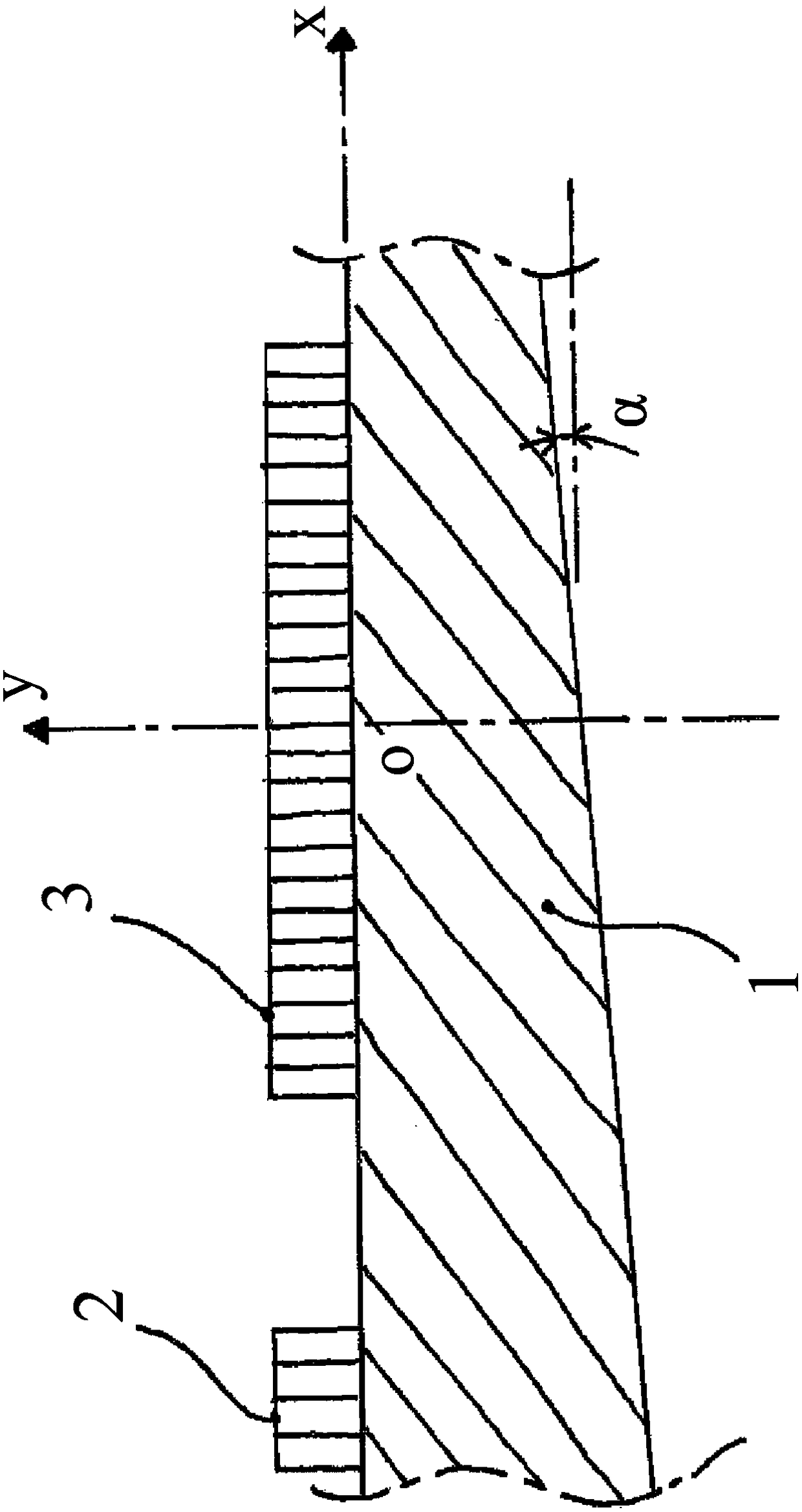
[0048] refer to figure 1 , in the orthonormal frame Oxyz in Euclidean space, the dihedral waveguide (1) is made of a material such as human bone or a phantom material of such bone such as glass fibers embedded in a commercially available epoxy material . The dihedral waveguide extends between a first plane xOz and a second plane passing through the points x=0, y=-e0, z=0, parallel to the axis Oz, and in projection in the plane xOy with the axis Ox forms an angle "α" or alpha=+2° angle, which is determined as the angles in the concept of direct trigonometry in the plane xOy. The waveguide thus has an x-dependent thickness e given by the formula: e(x)=e0·(1-tan(alpha)·x), e decreasing towards increasing x. For example, e0 is equal to 2.2mm.

[0049] A series of N (numerically equal to 5) emitters (2) are regularly deployed at the negative value of x on the x-axis at a pitch "A" of 0.8mm, and it is connected with a set of M (numerically equal to 24) The receivers (3) are sep...


PUM


Abstract

Device for the representation, in a frequency-wave number reference frame f-k, of the propagation of an ultrasound wave in a dihedral guide (1), which comprises ultrasound emitters (2) referenced by “Ej” with j an integer varying between 1 and N, N a strictly positive integer and ultrasound receivers (3) referenced by “Ri” with i an integer varying between 1 and M, M a strictly positive integer, the receivers being disposed spatially over a first segment of a straight line according to a regular pitch “A”, which comprises means for processing the signal received by the receivers, originating from the emitters, and in which the processing means comprise means for calculating a modified discrete spatial Fourier transform, for a spatial integration variable “x”, centered in the middle of said first segment and running through the receivers in the direction of increasing x, and for a wave vector k(x) equal to a product k.P(x), with k a constant coefficient in x and included between 0 and 2*Pi / A, and with P(x) a polynomial in x, of coefficient of degree 0 in x equal to 1 and of coefficient “C” of degree 1 in x such that C.A lies between − 1 / 10 and + 1 / 10

Description

technical field [0001] The present invention generally relates to characterizing the propagation of one or more ultrasonic waves in a waveguide or guided mode with a linearly variable waveguide thickness in a frequency-wavenumber framework. Background technique [0002] In particular, the invention relates to the characterization of one or more modes guided by the cortex or cortical portion of long human bones where the bone can be estimated by a linear variable thickness waveguide. The invention is especially aimed at aiding in the assessment of osteoporosis in a non-invasive manner by assessing the elastic and geometrical properties of the bone, especially the thickness, based on the characterization of the waveguide modes as a function of temporal frequency, based on relative wavenumber or relative phase velocity fracture risk. [0003] Hereinafter, "a polynomial of degree n of variable x" will represent the mathematical function f(x)=C 0 +C 1 ·x+…+C n x n , where C ...

Claims


Application Information

Patent Timeline
Patent Type & Authority Patents(China)
IPC IPC(8): G01N29/06A61B8/08G01S15/89
CPCG01N29/069A61B8/0875A61B8/4494A61B8/5207G01N2291/02483G01N2291/106
Inventor 卢多维克·莫罗简-加布丽埃勒·米农齐奥玛丽莱恩·塔尔芒帕斯卡尔·洛吉耶
Owner 爱莎莉
Why Eureka
Try Eureka