Eureka AIR delivers breakthrough ideas for toughest innovation challenges, trusted by R&D personnel around the world.

Angle sensing device and cloud platforms adopting the angle sensing device

A technology of angle sensing and rotation angle, applied in the field of gimbal, can solve the problems of increasing production cost, increasing positioning accuracy, over-positioning of potentiometer, etc., and reducing production cost.

Active Publication Date: 2016-04-20
SZ DJI OSMO TECH CO LTD
View PDF8 Cites 4 Cited by
  • Summary
  • Abstract
  • Description
  • Claims
  • Application Information

AI Technical Summary

Problems solved by technology

[0003] However, the rotating shaft mechanism of the above-mentioned angle sensing device is very easy to cause excessive positioning of the potentiometer, so that the drive shaft of the motor of the pan-tilt is not concentric with the detection hole of the potentiometer, so that there is a gap between the drive shaft of the motor of the pan-tilt and the angle sensor. Larger stress, which will cause the motor to rotate unsmoothly, affect the positioning accuracy and other problems
Therefore, during production and assembly, it is necessary to add a specific station to adjust the positioning accuracy between the drive shaft of the motor and the angle sensor, which increases the production cost

Method used


Image

  • Angle sensing device and cloud platforms adopting the angle sensing device
  • Angle sensing device and cloud platforms adopting the angle sensing device
  • Angle sensing device and cloud platforms adopting the angle sensing device

Examples


Embodiment Construction

[0060]The following will clearly and completely describe the technical solutions in the embodiments of the present invention with reference to the accompanying drawings in the embodiments of the present invention. Obviously, the described embodiments are only some, not all, embodiments of the present invention. Based on the embodiments of the present invention, all other embodiments obtained by persons of ordinary skill in the art without making creative efforts belong to the protection scope of the present invention.

[0061] It should be noted that when a component is said to be "fixed" to another component, it can be directly on the other component or there can also be an intervening component. When a component is said to be "connected" to another component, it may be directly connected to the other component or there may be intervening components at the same time. The terms "vertical," "horizontal," "left," "right," and similar expressions are used herein for purposes of i...


PUM


Abstract

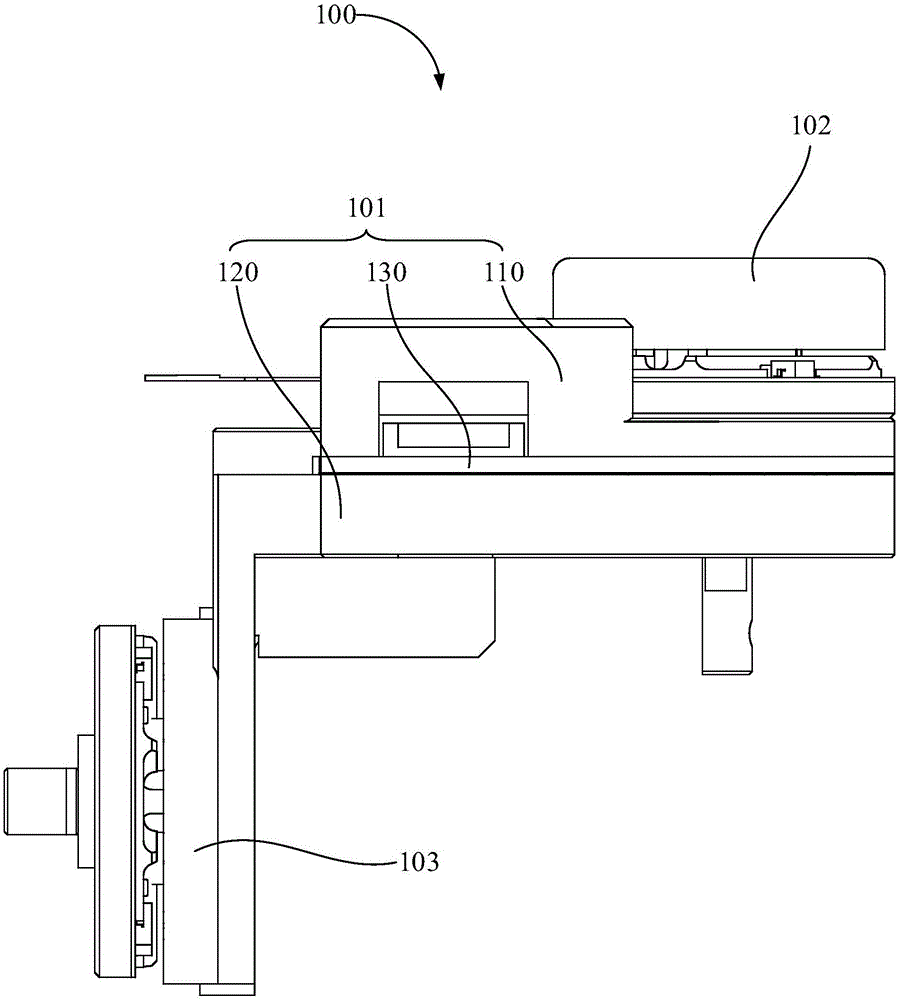
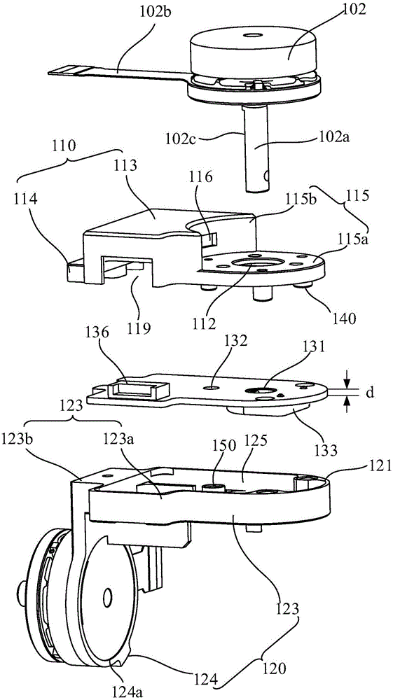
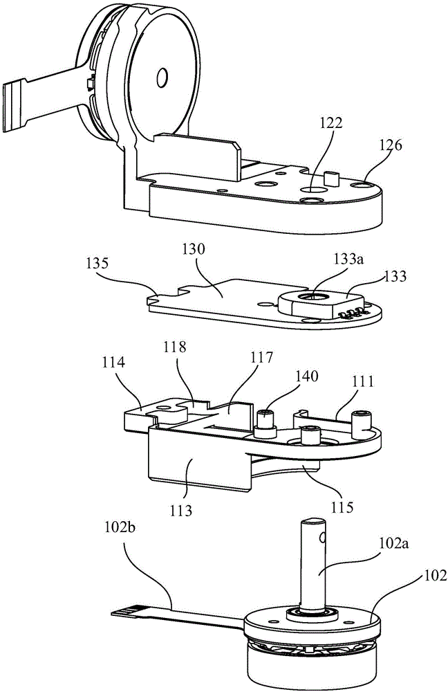
Disclosed are an angle sensing device (101) and cloud platforms (100, 200) adopting the angle sensing device (101). The angle sensing device comprises a rear cover (110) provided with an upper matching face (111), a support (120) provided with a lower matching face (121), and a sensor mounting plate (130) for mounting an angle sensor (133); the lower matching face (121) and the upper matching face (111) are disposed oppositely and are spaced at preset interval; and the sensor mounting plate (130) is disposed between the upper matching face (111) and the lower matching face (121), and the preset interval is greater than a thickness of the sensor mounting plate (130) so that the sensor mounting plate (130) can move between the upper matching face (111) and the lower matching face (121). The angle sensing device (101) can effectively reduce a stress between a drive shaft of a motor and the angle sensor (133) on the sensor mounting plate (130), so production cost of the cloud platforms (100, 200) is saved.

Description

technical field [0001] The invention relates to an angle sensing device, in particular to an angle sensing device for sensing the rotation angle of a drive shaft of a motor and a pan tilt adopting the angle sensing device. Background technique [0002] The traditional gimbal angle sensing device integrates the potentiometer on the ESC board as the angle sensor. In order to fix the ESC board, the rotating shaft mechanism uses the bracket and the back cover to clamp the ESC board, and the periphery of the ESC board is exposed outside the bracket and the back cover. [0003] However, the rotating shaft mechanism of the above-mentioned angle sensing device is very easy to cause excessive positioning of the potentiometer, so that the drive shaft of the motor of the pan-tilt is not concentric with the detection hole of the potentiometer, so that there is a gap between the drive shaft of the motor of the pan-tilt and the angle sensor. Larger stress will cause the motor to rotate u...

Claims


Application Information

Patent Timeline
Patent Type & Authority Applications(China)
IPC IPC(8): H02K11/00G01B21/22
CPCG01D11/245F16M11/18G05D3/00G01B7/30
Inventor 陈子涵潘大虎鄢奇龙
Owner SZ DJI OSMO TECH CO LTD
Why Eureka
Eureka Blog
Learn More