
Ash scraping device for hot-dip galvanizing before dip plating
A technology of hot-dip galvanizing and scraper, which is applied in the direction of hot-dip galvanizing, coating, metal material coating technology, etc., and can solve the problem of constant height or readjusting the position of scraper every time dusting, without considering zinc Problems such as the drop of zinc liquid in the pot and the unsteady control of the depth of the zinc rake can achieve the effect of shortening the time used for ash removal, avoiding the randomness of the immersion depth, and improving the efficiency of ash removal
- Summary
- Abstract
- Description
- Claims
- Application Information
AI Technical Summary
Problems solved by technology
Method used
Image

Examples
Embodiment 1
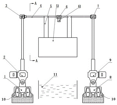
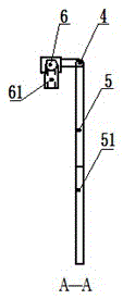
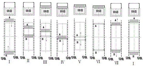
[0022] The dust scraping device before hot-dip galvanizing and galvanizing described in this embodiment includes an electric trolley I1, an electric push rod I2, a reduction motor 3, a rotating shaft 4, a scraper 5, an infrared detector 6, a bearing support 7, and an electric trolley II8 , electric push rod Ⅱ9, guide rails 10 are provided on both sides of the zinc pot 11, electric trolley Ⅰ1 and electric trolley Ⅱ8 are respectively arranged on the guide rail 10, electric trolley Ⅰ1 and electric trolley Ⅱ8 are respectively connected with electric push rod Ⅰ2 and electric push rod Ⅱ9 The lower end is connected; the deceleration motor 3 is fixed on the upper end of the electric push rod I2, the output shaft of the deceleration motor 3 is connected with the rotating shaft 4, and the other end of the rotating shaft 4 is fixed on the bearing support 7, and the bearing support 7 is fixed on the electric push rod II9. On the telescopic rod; below the rotating shaft 4, there is a scrape...
Embodiment 2
[0025] The dust scraping device before hot-dip galvanizing and galvanizing described in this embodiment includes an electric trolley I1, an electric push rod I2, a reduction motor 3, a rotating shaft 4, a scraper 5, an infrared detector 6, a bearing support 7, and an electric trolley II8 , electric push rod Ⅱ9, guide rails 10 are provided on both sides of the zinc pot 11, electric trolley Ⅰ1 and electric trolley Ⅱ8 are respectively arranged on the guide rail 10, electric trolley Ⅰ1 and electric trolley Ⅱ8 are respectively connected with electric push rod Ⅰ2 and electric push rod Ⅱ9 The lower end is connected; the deceleration motor 3 is fixed on the upper end of the electric push rod I2, the output shaft of the deceleration motor 3 is connected with the rotating shaft 4, and the other end of the rotating shaft 4 is fixed on the bearing support 7, and the bearing support 7 is fixed on the electric push rod II9. On the telescopic rod; below the rotating shaft 4, there is a scrape...
Embodiment 3
[0028] The dust scraping device before hot-dip galvanizing and galvanizing described in this embodiment includes an electric trolley I1, an electric push rod I2, a reduction motor 3, a rotating shaft 4, a scraper 5, an infrared detector 6, a bearing support 7, and an electric trolley II8 , electric push rod Ⅱ9, guide rails 10 are provided on both sides of the zinc pot 11, electric trolley Ⅰ1 and electric trolley Ⅱ8 are respectively arranged on the guide rail 10, electric trolley Ⅰ1 and electric trolley Ⅱ8 are respectively connected with electric push rod Ⅰ2 and electric push rod Ⅱ9 The lower end is connected; the deceleration motor 3 is fixed on the upper end of the electric push rod I2, the output shaft of the deceleration motor 3 is connected with the rotating shaft 4, and the other end of the rotating shaft 4 is fixed on the bearing support 7, and the bearing support 7 is fixed on the electric push rod II9. On the telescopic rod; below the rotating shaft 4, there is a scrape...
PUM
 Abstract
Description
Claims
Application Information