Pipe rod dragging method and device

A technology of dragging device and pipe rod, applied in drill pipe, drill pipe, casing and other directions, can solve the problems of high labor intensity of workers and large weight of pipe rod, etc., to improve the reliability of locking, reduce labor intensity, and facilitate the removed effect

Inactive Publication Date: 2016-04-27
CHINA PETROLEUM & CHEM CORP +1
View PDF8 Cites 5 Cited by
  • Summary
  • Abstract
  • Description
  • Claims
  • Application Information

AI Technical Summary

Problems solved by technology

Due to the generally large weight of pipe rods, the labor intensity of workers is relatively high during the deflection process

Method used


Image

  • Pipe rod dragging method and device
  • Pipe rod dragging method and device

Examples


Embodiment Construction

[0015] The detailed description and technical content of the present invention are described below with the accompanying drawings, but the accompanying drawings are only provided for reference and description, and are not intended to limit the present invention.

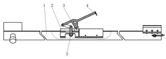
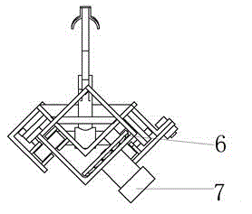
[0016] according to Figure 1-2 , a pipe rod dragging device, including a slideway 1, a trolley 2, a locking mechanism 3, a gripper 4, a sliding pin 5, and traction and power components. The trolley 2 is installed in the slideway 1 and can slide freely relative to the slideway 1. Wherein traction mechanism is sprocket wheel chain mechanism 6, and it directly links to each other with sliding pin 5, and sliding pin 5 is installed in the middle groove of trolley 2, and can have relative motion with trolley. The buckle-lock link mechanism 3 is respectively hinged with the slide pin 5 and the trolley 2, and can complete the snap-lock action through the relative motion of the slide pin 5 and the trolley 2. The gripper 4 ...


PUM


Abstract

The invention discloses a pipe rod dragging method and device. The pipe rod dragging device comprises a slideway, a small pulley, a lock buckle mechanism and a driving traction mechanism, wherein the small pulley is assembled on the slideway and can operate on the slideway to and fro; the lock buckle mechanism is arranged on the small pulley; and the driving traction mechanism is arranged at two ends of the slideway. The lock buckle mechanism is a crank connecting rod mechanism, and comprises a lock buckle main body, a gripping hand and a slide pin; the middle bottom of the lock buckle main body is hinged onto the small pulley; a slide groove opening is formed in the small pulley; the slide pin is arranged in the slide groove opening and can move in the slide groove to and fro; the upper end of the slide pin passes through two sequentially hinged connecting rods and is then finally hinged to the lower end of the lock buckle main body; and the top end of the lock buckle main body is provided with the gripping hand. The method and the device have the advantage that the pipe rod dragging action of pipe rods such as drilling rods, sucker rods and oil pipes on the horizontals and inclined slideway during horizontal row pulling can be mechanistically realized.

Description

technical field [0001] The invention relates to a mechanized lifting and lowering device for oil and water wells in an oil field, in particular to a pipe rod dragging method and device. Background technique [0002] When lifting and lowering the pipe string in the workover operation of conventional oil and water wells, the pipe rod is in a vertical state after being pulled out and undocked. Well small pulley, and manually pull the inclined pipe rod. Because the weight of pipe rods is generally large, the labor intensity of workers is relatively high during the deflection process. Contents of the invention [0003] The object of the present invention is to provide a method and device for pulling pipes and rods, which can mechanize the pulling action of pipes and rods such as drill pipes, sucker rods and oil pipes when they are pulled horizontally on horizontal and inclined slideways. [0004] In order to achieve the above object, the present invention adopts the following...

Claims


Application Information

Patent Timeline
Patent Type & Authority Applications(China)
IPC IPC(8): E21B19/14
Inventor 高广启张雷宋辉辉张辉唐倩雯苏秋涵付增
Owner CHINA PETROLEUM & CHEM CORP
Why Eureka
Try Eureka