Dual laterolog equipment, electrode system of dual laterolog equipment and formation resistivity measuring method

A dual laterolog and formation resistivity technology, which is applied in the directions of measurement, earthwork drilling and production, borehole/well components, etc., can solve problems such as difficulty in achieving measurement accuracy and failure to solve the influence of vertical potential gradient

Active Publication Date: 2016-04-27
CNPC GREATWALL DRILLING ENG +1
View PDF9 Cites 12 Cited by
  • Summary
  • Abstract
  • Description
  • Claims
  • Application Information

AI Technical Summary

Problems solved by technology

Although the high-resolution azimuthal resistivity logging tool and logging method adopt digital focus mode and hard focus mode, compared with the original hard focus The method of short-circuiting the

Method used


Image

  • Dual laterolog equipment, electrode system of dual laterolog equipment and formation resistivity measuring method
  • Dual laterolog equipment, electrode system of dual laterolog equipment and formation resistivity measuring method
  • Dual laterolog equipment, electrode system of dual laterolog equipment and formation resistivity measuring method

Examples


Embodiment 1

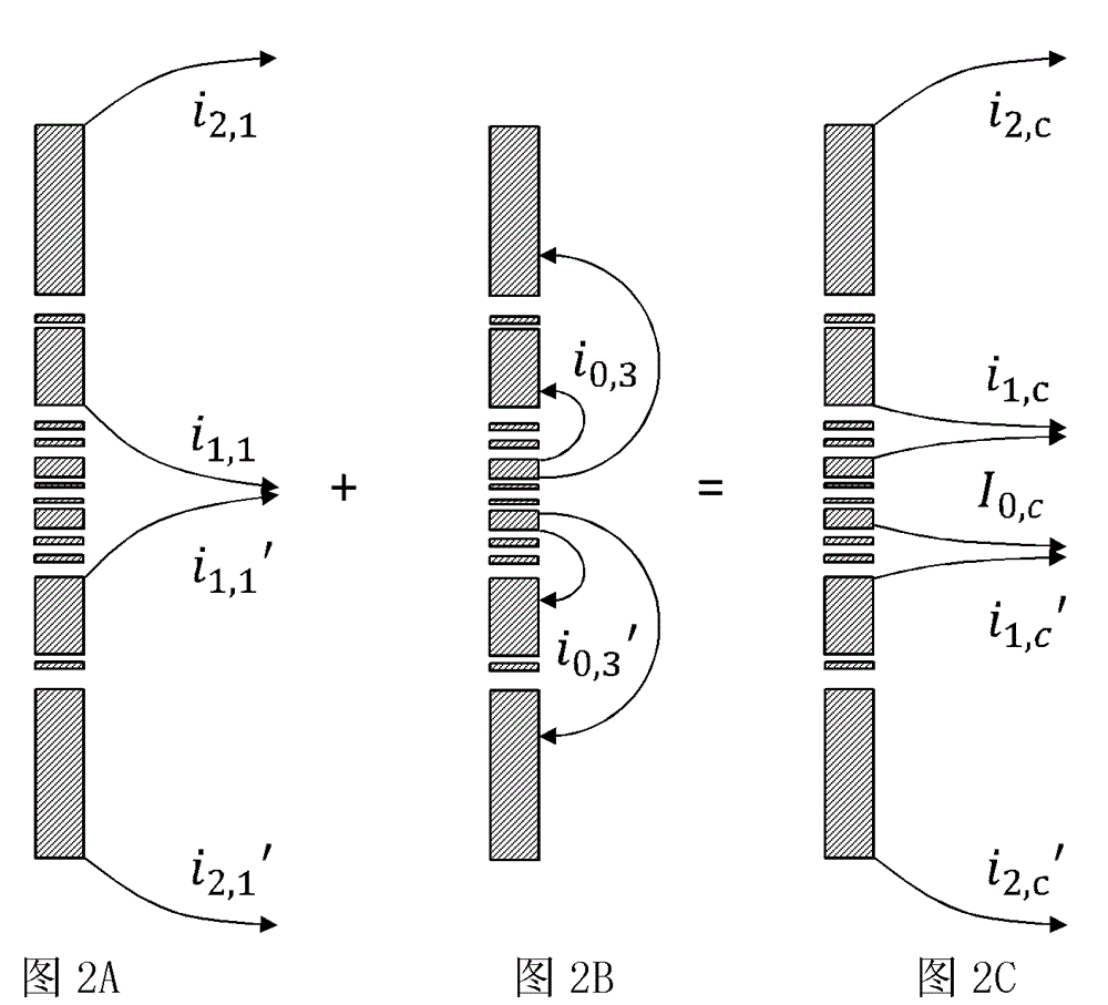
[0060] figure 2 C is the deep laterolog mode synthesized by the high-resolution dual laterolog tool of the present invention. The formation apparent resistivity can be calculated by using the data collected in the above three working modes. as attached figure 2 As shown in C, using the combination of mode 1 and mode 3, the deep lateral apparent resistivity can be obtained:

[0061]

[0062] in, is the deep lateral instrument coefficient,

[0063]

[0064]

[0065]

[0066]

[0067] .

Embodiment 2

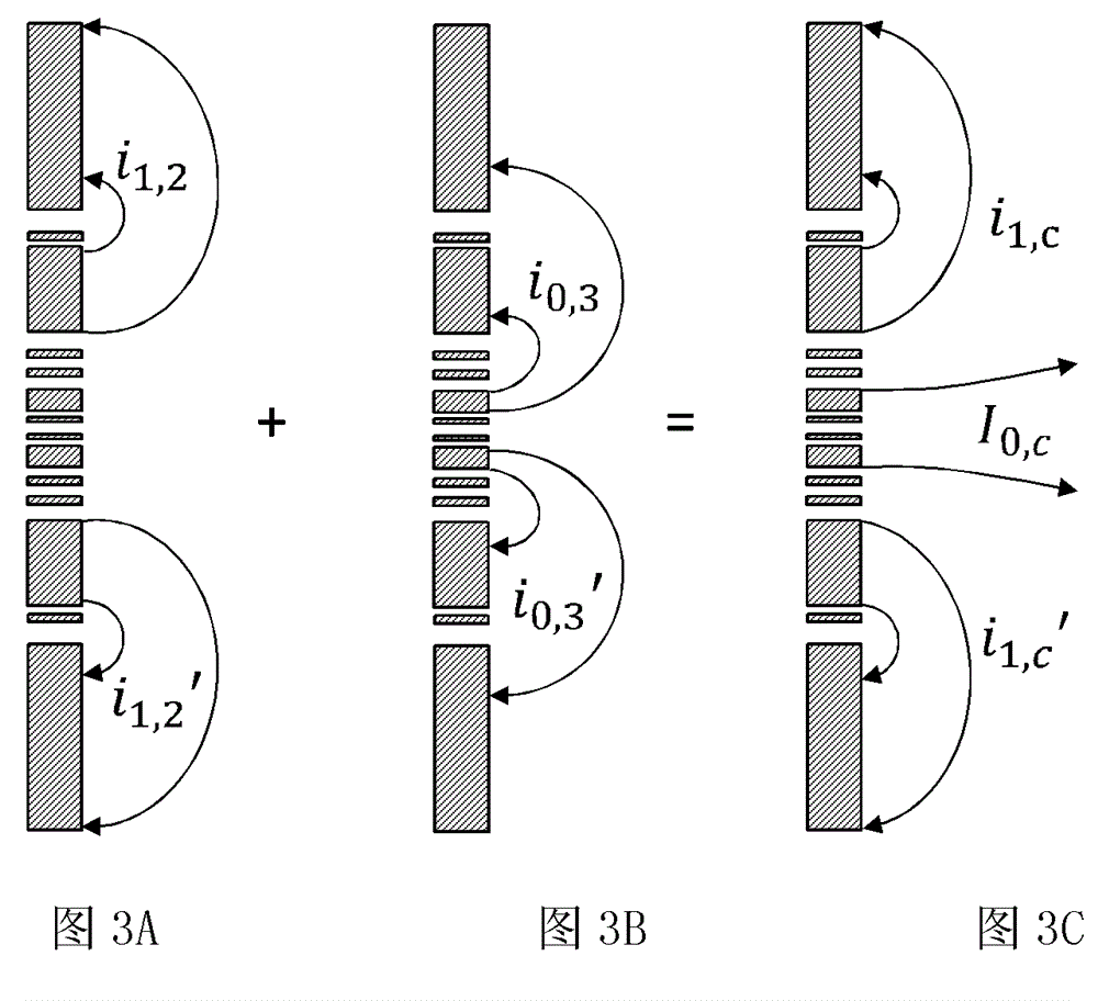
[0069] image 3 C is the shallow laterolog mode synthesized by the high-resolution dual laterolog tool of the present invention. The formation apparent resistivity can be calculated by using the data collected in the above three working modes. as attached image 3 As shown in C, the shallow lateral apparent resistivity can be obtained by using the combination of mode 2 and mode 3:

[0070]

[0071] in, is the shallow lateral instrument coefficient,

[0072]

[0073] .

[0074] Using the data collected in the above three working modes, the following high-resolution deep and shallow lateral apparent resistivity curves can also be calculated:

[0075]

[0076]

[0077] in, , are high-resolution deep and shallow lateral instrument coefficients, respectively,

[0078]

[0079]

[0080]

[0081]

[0082]

[0083]

[0084] .

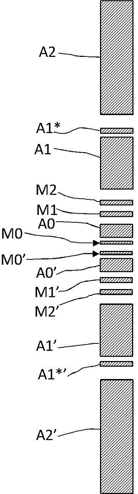
[0085] In the present invention, electrodes A2 and A2' are short-circuited, electrodes A0 and A0' are short-circu...


PUM


Abstract

The invention relates to dual laterolog equipment, an electrode system of the dual laterolog equipment and a formation resistivity measuring method. The electrode system comprises an electrode system body and an insulation core rod, consists of a plurality of electrodes arranged on one insulation core rod, and is connected with a measuring circuit through a conducting wire; insulation materials are used for separating the plurality of electrodes; the center of the insulation core rod is a metal rod; a through hole is formed in the center of the metal rod; the metal rod is isolated from the electrode system; the electrode system comprises main electrodes A0 and A0', at least one pair of shielding electrodes A2, A2', A1 and A1', a plurality of pairs of voltage measuring electrodes A1*, A1*', M0 and M0' and at least one pair of voltage monitoring electrodes M2, M2', M1 and M1', wherein the main electrodes A0 and A0' are arranged in the middle of the electrode system; the shielding electrodes A2, A2', A1 and A1' are used for emitting shielding current for focusing main current; the voltage measuring electrodes A1*, A1*', M0 and M0' are used for measuring electrode voltage; the voltage monitoring electrodes M2, M2', M1 and M1' are used for voltage monitoring; the shielding electrodes A2 and A2 are in short-circuit connection; the main electrodes A0 and A0' are in short-circuit connection; and other electrodes are not in short-circuit connection. Therefore compared with a hard focusing mode, the electrode system has high measuring precision.

Description

technical field [0001] The invention relates to a well logging device used for petroleum exploration and development, in particular to a double lateral logging instrument, its electrode system, and a formation resistivity measurement method. Background technique [0002] Dual laterolog tool is the main instrument for measuring formation resistivity in open hole, studying formation invasion changes, and estimating oil saturation. The traditional dual laterolog tool mainly includes electrode system, electronic circuit, and insulating nipple. The resolution is about 0.6 meters. When the traditional dual laterolog tool performs deep lateral logging, the annular electrode emits current into the formation, and the cylindrical electrode emits shielding current to focus on the main current. A feedback loop is required in the electronic circuit to adjust the shielding current, and the control monitoring electrode is at Equipotential. For example, Chinese patent CN1712995A disclose...

Claims


Application Information

Patent Timeline
IPC IPC(8): E21B49/00E21B47/00
Inventor 胡海涛白庆杰肖占山张森峰高秀晓姚春明朱瑞明于振南邵琨
Owner CNPC GREATWALL DRILLING ENG
Why Eureka
Try Eureka