Exhaust gas treatment device

An exhaust gas treatment device and exhaust gas treatment technology, which are applied in the electrical control of exhaust treatment devices, exhaust gas treatment, gas treatment, etc., can solve the problems of untreated exhaust gas, inaccurate measurement signals, and cumbersome structure of exhaust gas treatment boxes, etc. , to achieve the effect of simplified structure and accurate measurement signal

Active Publication Date: 2018-05-22
CHANGZHOU DEV & MFR CENT
View PDF5 Cites 0 Cited by
  • Summary
  • Abstract
  • Description
  • Claims
  • Application Information

AI Technical Summary

Problems solved by technology

When there is no water in the supplementary water tank, even if the water level of the large water tank is low, no water can be filled into the small water tank, resulting in the water level of the large water tank not reaching the standard, and the exhaust gas cannot be treated
Untreated waste gas is not allowed to be discharged underground in coal mines. For this reason, the above-mentioned utility model is equipped with a water level sensor in the large water tank to feed back the water volume of the large water tank. However, the structure of the waste gas treatment tank is cumbersome, and the sewage in the large water tank It will make it difficult for the float of the water level sensor to move up and down along the measuring tube, and the measuring signal is not accurate

Method used


Image

  • Exhaust gas treatment device

Examples


Embodiment 1

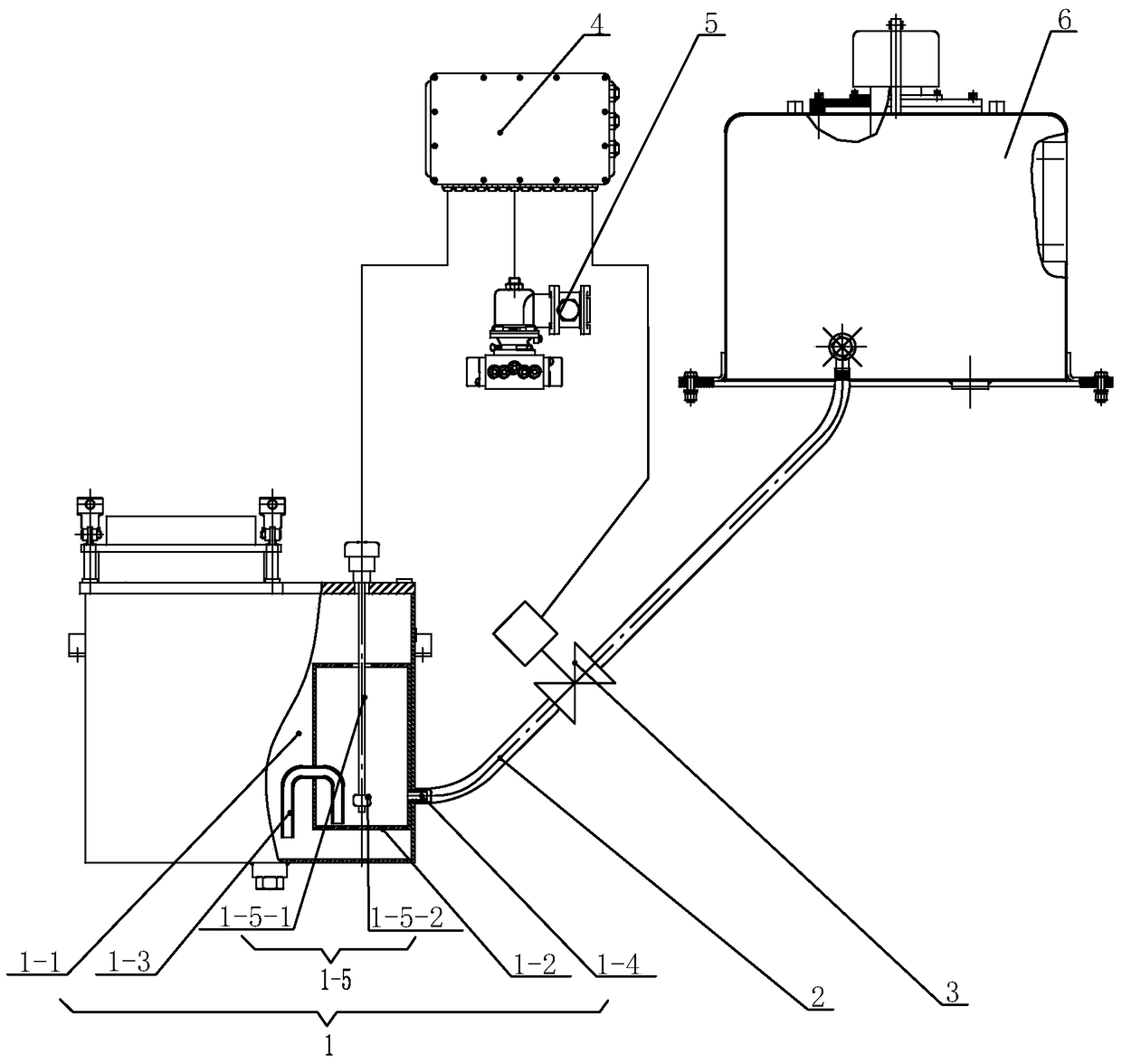
[0009] See figure 1 , an exhaust gas treatment device, comprising an exhaust gas treatment box 1, a water replenishment pipe 2, a water solenoid valve 3, a monitoring host 4, a flameout cylinder solenoid valve 5 and a water replenishment tank 6. The exhaust gas treatment tank 1 includes a large water tank 1-1 and a small water tank 1-2, the small water tank 1-2 is located in the large water tank 1-1, and the small water tank 1-2 and the large water tank 1-1 are connected by a siphon 1-3, When the water level in the small water tank 1-2 is higher than the water level in the large water tank 1-1, the water in the small water tank 1-2 is filled into the large water tank 1-1 through the siphon 1-3, and the top surface of the large water tank 1-1 is fixed A water level sensor 1-5, the detection tube 1-5-1 and the float 1-5-2 of the water level sensor 1-5 are inserted in the small water tank 1-2, and the float 1-5-2 is inserted into the small water tank 1-2 The water level slides u...


PUM


Abstract

The invention relates to a waste gas treatment device. The waste gas treatment device comprises a waste gas treatment box, a water supplementing pipe, a monitoring host, a flameout air cylinder electromagnetic valve and a water supplementing box; the water supplementing pipe is connected between the waste gas treatment box and the water supplementing box; and the waste gas treatment box comprises a large water tank, a small water tank, a siphon, a connector and a water level sensor, the water level sensor is connected with an electrical controller in the monitoring host through a signal line, a control line of an electromagnetic valve for water is connected with the electrical controller of the monitoring host, and the electrical controller of the monitoring host is connected with a control line for controlling the flameout air cylinder electromagnetic valve of a flameout air cylinder. According to the waste gas treatment device, the water level sensor is arranged in the small water tank to replace a floating ball water level control mechanism and a water level sensor in the large water tank, and therefore the structure of the waste gas treatment device is simplified. According to the waste gas treatment device, a timer in the monitoring host is used, when set time is up, the flameout air cylinder electromagnetic valve is controlled by the electrical controller to be closed, an engine flames out, no waste gas is generated by the engine, and it is guaranteed that the waste gas which is not treated is not exhausted.

Description

technical field [0001] The invention relates to an exhaust gas treatment device. Background technique [0002] The coal mine underground vehicle cools and washes the exhaust gas from the engine through the exhaust gas treatment box, removes the carbon smoke and some harmful gases in the dissolved exhaust gas, and extinguishes the flame in the exhaust gas through the explosion-proof fence to ensure the safety of the exhaust. China's authorized announcement number is CN203978574U utility model patent specification discloses a kind of exhaust gas treatment box for coal mine underground vehicles, including a large water tank and a small water tank. The water in the small water tank enters the large water tank through a siphon tube. The float water level control mechanism is connected with the water supply pipe. The water supply pipe is generally connected to the water supply tank on the vehicle. The installation height of the water supply tank on the vehicle is higher than that...

Claims


Application Information

Patent Timeline
Patent Type & Authority Patents(China)
IPC IPC(8): F01N3/04F01N9/00F02D17/04B01D47/02B01D53/78B01D53/92
CPCB01D47/02B01D53/78B01D53/92B01D2258/01F01N3/04F01N9/00F01N2430/02F01N2590/08F01N2610/1406F02D17/04Y02T10/40
Inventor 刘开华方文杰赵雅
Owner CHANGZHOU DEV & MFR CENT
Why Eureka
Try Eureka