Grouting simulating test device and test method thereof

A simulation test and grouting technology, applied in the direction of measuring devices, using stable tension/pressure testing material strength, instruments, etc., can solve the problems of difficult control of working conditions, complex properties of grout, and difficult control of implementation effects, etc., to achieve Effect of preventing eccentric compression

Inactive Publication Date: 2016-04-27
SHANDONG UNIV
View PDF9 Cites 47 Cited by
  • Summary
  • Abstract
  • Description
  • Claims
  • Application Information

AI Technical Summary

Problems solved by technology

However, due to the uncertainty of formation conditions and the complexity of grout properties, the existing theoretical research on grouting greatly lags behind the engineering application requirements, and most of the grouting parameters need to be determined through grouting tests. The important means of grouting parameters and the influence of various factors on the grouting effect
However, indoor grouting tests are often limited by factors such as the size of the model device, the large amount of filling work, the difficulty in controlling the working conditions, the difficulty in simulating the water content of the formation, and the invisible grouting effect, which

Method used


Image

  • Grouting simulating test device and test method thereof
  • Grouting simulating test device and test method thereof
  • Grouting simulating test device and test method thereof

Examples


Embodiment Construction

[0037] Below in conjunction with accompanying drawing and embodiment the present invention is further described:

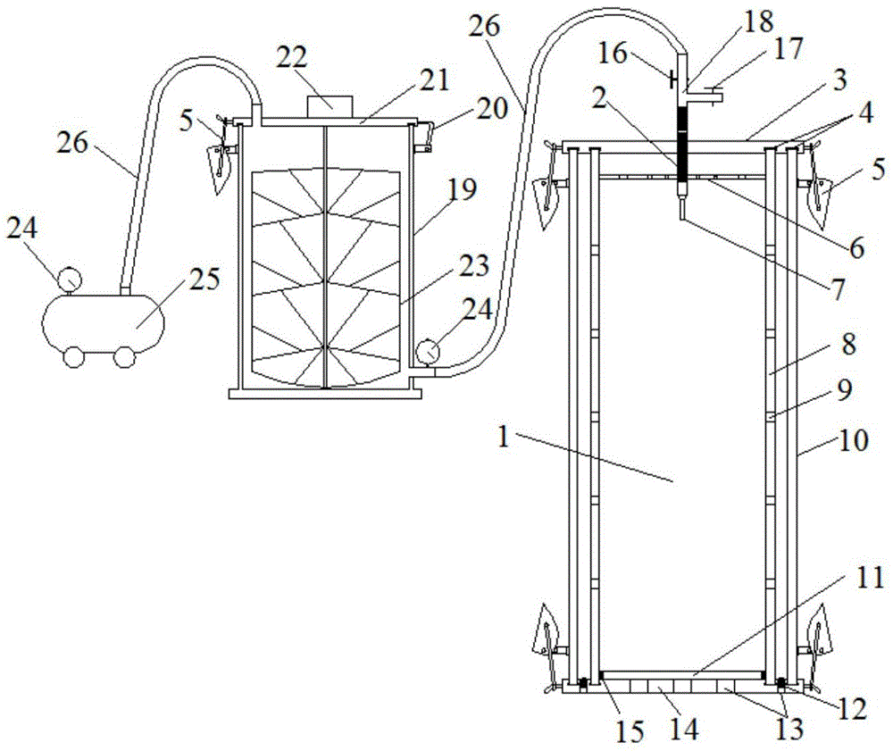
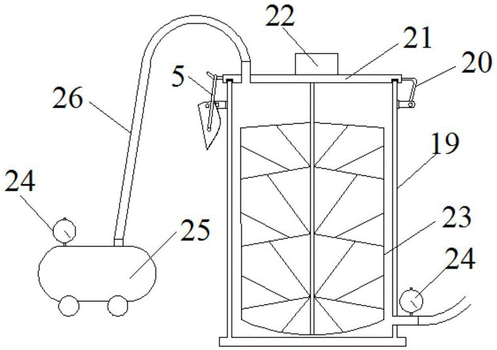
[0038] Examples of the present invention provide a kind of grouting simulation test device, such as figure 1 As shown, the device includes a pressurization system and a grouting penetration device.

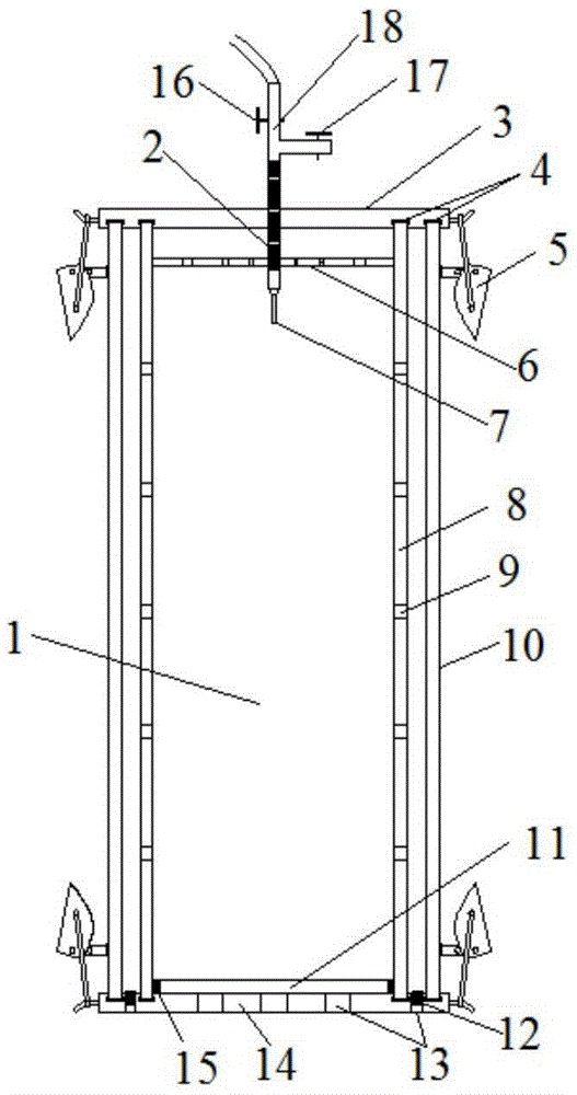
[0039] like figure 2 As shown, the grouting penetration device includes: a grouting chamber 1, a top cover 3, a sealing buckle 5, a porous isolation plate 6, a grouting nozzle 7, an inner cylinder 8, an outer cylinder 10, a base 14, a slurry control valve 16, a Water valve 17. The top cover 3 and the base 14 are respectively connected to the outer cylinder 10 through four symmetrically distributed sealing buckles, grooves are provided on the connection contact surfaces, and the sealing rubber pad 4 is built in, and the external threaded grouting pipe 2 is isolated from the porous The contact surfaces of the plate 6 and the top cover 3 have threads that match each ...


PUM


Abstract

The invention discloses a grouting simulating test device and a test method thereof, and belongs to the field of indoor grouting simulating test. The grouting simulating test device comprises a pressurizing system and a grouting permeating device, wherein the pressurizing system comprises a pressurizing air pump, a mortar storage bucket and a pressure gauge, a stirrer is arranged in the mortar storage bucket, and the upper part and lower part of the mortar storage bucket are respectively provided with a mortar inlet and a mortar outlet which are communicated with the pressurizing air pump and the grouting permeating device; the grouting permeating device comprises an inner cylinder and an outer cylinder, and water permeating holes are distributed in the wall of the inner cylinder; a grouting pipe is arranged at the top part of the grouting permeating device and extends into the grouting permeating device, the exterior of the grouting pipe is provided with external threads, and a porous separating plate is sheathed at the exterior of the grouting pipe, and can move vertically; holes are formed in the bottom part of the grouting permeating device, and the upper part of the grouting permeating device is provided with water permeating stones. The grouting simulating test device has the advantages that the grouting simulating test device can be used for grouting simulating test of multiple soil layer overlying conditions, different filling and building conditions and water-containing soil conditions; the operation of the test method is simple, multiple working conditions can be simulated, the grouting simulating effect is approximate to the actual condition, and the grouting effect is visual and visible.

Description

technical field [0001] The invention relates to the field of grouting tests, in particular to a grouting simulation test device and a test method thereof. Background technique [0002] In recent years, grouting technology, as a highly professional construction method, has been used more and more in the reinforcement and treatment of weak ground due to its simple process, fast construction speed and low engineering cost. However, due to the uncertainty of formation conditions and the complexity of grout properties, the existing theoretical research on grouting greatly lags behind the engineering application requirements, and most of the grouting parameters need to be determined through grouting tests. It is an important means of grouting parameters and various factors affecting the law of grouting effect. However, indoor grouting tests are often limited by factors such as the size of the model device, the large amount of filling work, the difficulty in controlling the workin...

Claims


Application Information

Patent Timeline
IPC IPC(8): G01N33/00G01N3/08
CPCG01N3/08G01N33/00
Inventor 宋修广王丽娜张宏博岳红亚崔兵兵王珂
Owner SHANDONG UNIV
Why Eureka
Try Eureka