Dehumidifying method and system

A technology of humidity and humidity value, applied in control/regulation systems, humidity control, non-electric variable control, etc., can solve problems such as frequent occurrence of power grid accidents in substation equipment

Inactive Publication Date: 2016-04-27
STATE GRID ZHEJIANG NINGBO FENGHUA POWER SUPPLY CO LTD +2
View PDF9 Cites 2 Cited by
  • Summary
  • Abstract
  • Description
  • Claims
  • Application Information

AI Technical Summary

Problems solved by technology

[0004] In view of this, the purpose of the embodiments of the present invention is to provide a dehumidification method and system to control the dryness in the control box of the substati

Method used


Image

  • Dehumidifying method and system
  • Dehumidifying method and system
  • Dehumidifying method and system

Examples


Embodiment 1

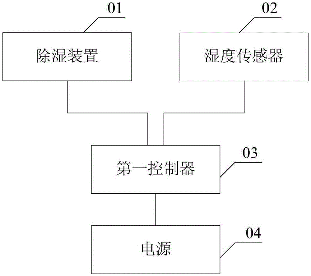
[0031] figure 1 It is a schematic structural diagram of a dehumidification system provided in Embodiment 1 of the present application.

[0032] Such as figure 1 As shown, the system includes:

[0033] Dehumidification device 01;

[0034] Humidity sensor 02 for detecting the humidity value of the gas in the control box;

[0035] One end is connected to the humidity sensor 02, and the other end is connected to the dehumidification device 01, which is used to control the first controller 03 of the dehumidification device to adjust the humidity of the gas in the control box by using the humidity value detected by the humidity sensor;

[0036] A power supply 04 connected to the first controller 03.

[0037] Preferably, the first controller uses the humidity value detected by the humidity sensor to control the dehumidification device to adjust the humidity of the gas in the control box: judge whether the obtained humidity value detected by the humidity sensor is higher than the ...

Embodiment 2

[0056] Figure 5 It is a flowchart of a dehumidification method provided in Example 2 of the present application.

[0057] Such as Figure 5 As shown, the method includes:

[0058] S101. The first controller acquires the humidity value of the gas in the control box detected by the humidity sensor.

[0059] Specifically, the dehumidification method provided in the embodiment of the present application is provided on the basis of the dehumidification system provided in the first embodiment above.

[0060] S102. Using the humidity value to control the dehumidification device to adjust the humidity of the gas in the control box.

[0061] Specifically, after the first controller obtains the humidity value of the gas in the control box detected by the humidity sensor, it will use the humidity value to control the dehumidification device to adjust the humidity of the gas in the control box.

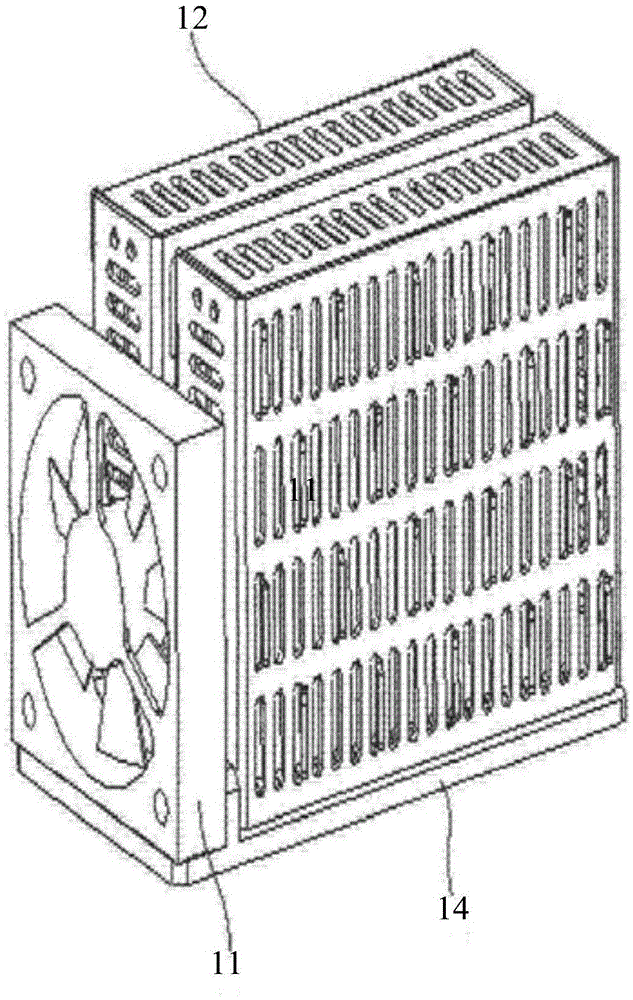
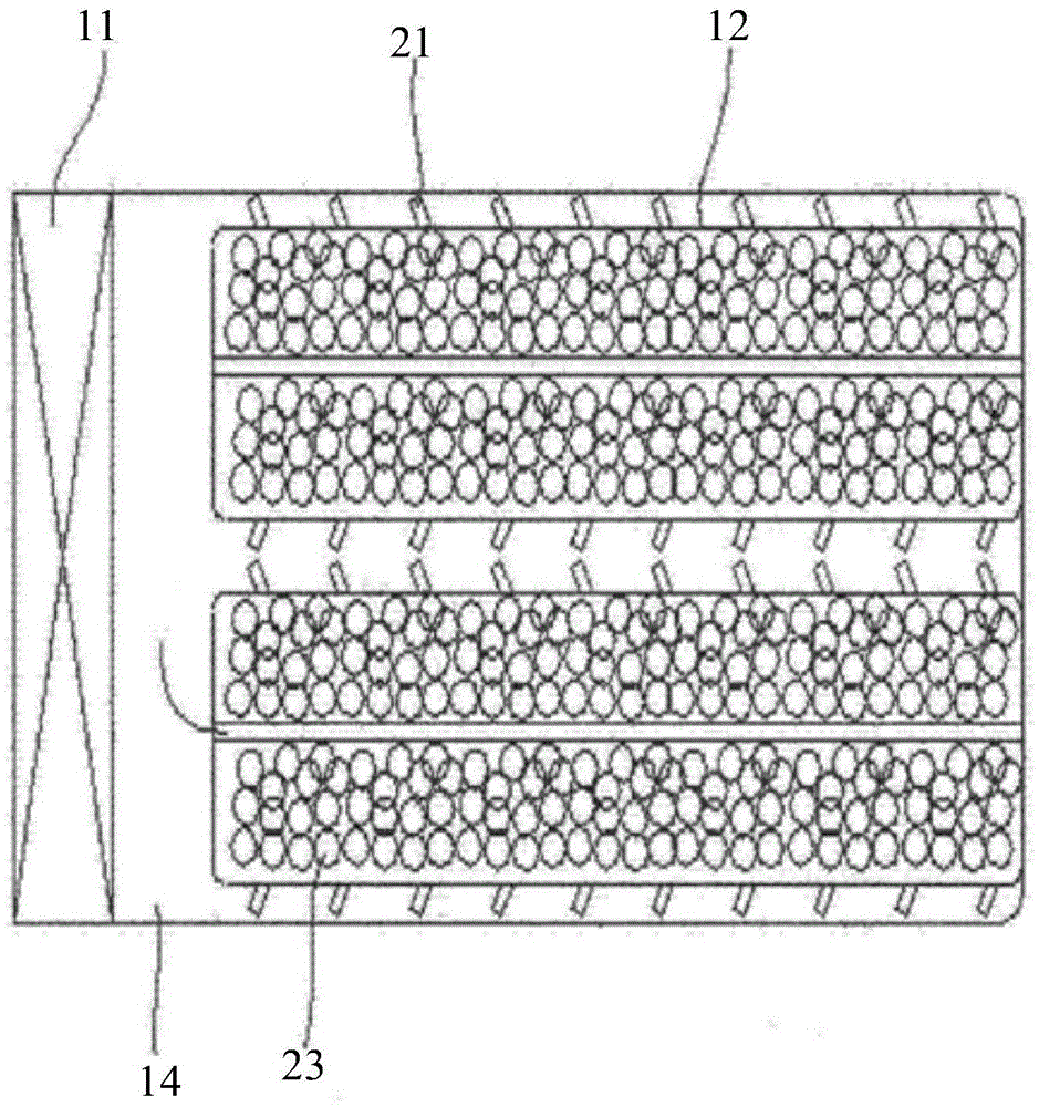
[0062] Specifically, the dehumidification device includes: at least one set of dehumidif...


PUM


Abstract

The invention provides a dehumidifying method and system. A humidity sensor detects the humidity value of gas in a control box, and a first controller controls a dehumidifying device with the humidity value detected by the humidity sensor to adjust the humidity of gas in the control box, thus controlling the dryness in the control box of transformer equipment, and solving the problem of frequent grid accidents caused by the reason that components in the control box are easily damped to influence the safety operation of the transformer equipment.

Description

technical field [0001] The present invention relates to the technical field of power equipment, and more specifically, to a dehumidification method and system. Background technique [0002] Various electronic components are installed in the control boxes of power transformation equipment such as high-voltage cabinets, indoor / outdoor switches, knife control boxes, and power boxes to realize various control and execution functions. In order to ensure the reliability of the use and service life of the substation equipment, the control box of this type of substation equipment has strict requirements on the dryness of the working environment. [0003] The components in the control box of the substation equipment are prone to moisture when the weather changes, which will cause the rotating part of the substation equipment to fail when performing work, the insulation resistance will drop, resulting in electrical breakdown, and the secondary terminals may be poorly connected or shor...

Claims


Application Information

Patent Timeline
IPC IPC(8): G05D22/02
CPCG05D22/02
Inventor 何君杰裘建开母国辉张明达
Owner STATE GRID ZHEJIANG NINGBO FENGHUA POWER SUPPLY CO LTD
Why Eureka
Try Eureka