
Current-limiting solid-state circuit breaker for actively suppressing overvoltage and control method thereof

A solid-state circuit breaker, active suppression technology, applied in emergency protection circuit devices, circuit devices, emergency protection circuit devices, etc. for limiting overcurrent/overvoltage, can solve problems such as not fundamentally eliminating overvoltage

Inactive Publication Date: 2016-04-27
CHINA UNIV OF MINING & TECH (BEIJING)
View PDF8 Cites 20 Cited by
  • Summary
  • Abstract
  • Description
  • Claims
  • Application Information

AI Technical Summary

Problems solved by technology

At present, the overvoltage protection in solid-state circuit breakers mainly relies on two methods: resistance-capacitance snubber circuit and zinc oxide lightning rod. These two methods are passive protection against overvoltage, and do not fundamentally eliminate the cause of overvoltage.

Method used

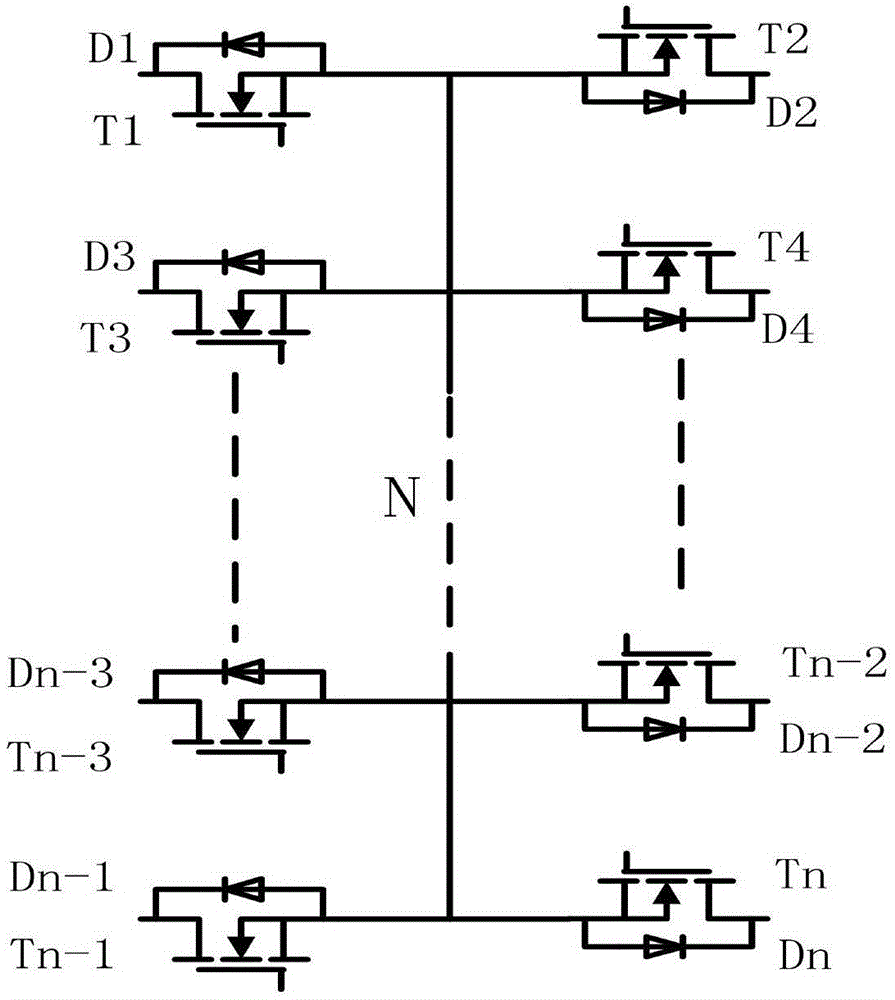
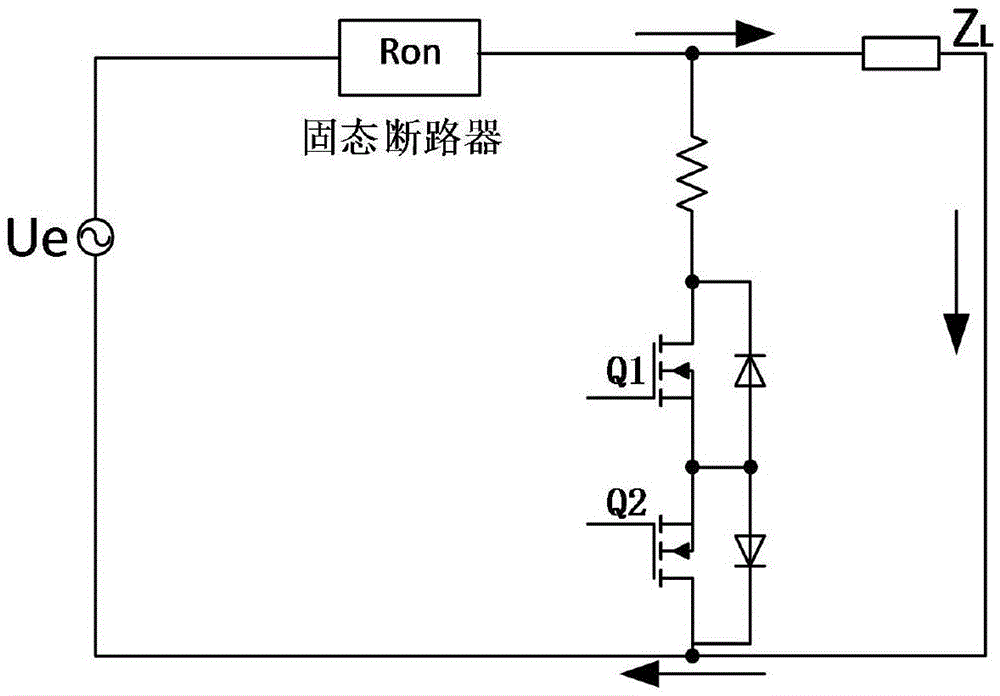

Image

  • Current-limiting solid-state circuit breaker for actively suppressing overvoltage and control method thereof
  • Current-limiting solid-state circuit breaker for actively suppressing overvoltage and control method thereof
  • Current-limiting solid-state circuit breaker for actively suppressing overvoltage and control method thereof

Examples


Embodiment Construction

[0028] specific implementation plan

[0029] The present invention will be described in further detail below in conjunction with the accompanying drawings.

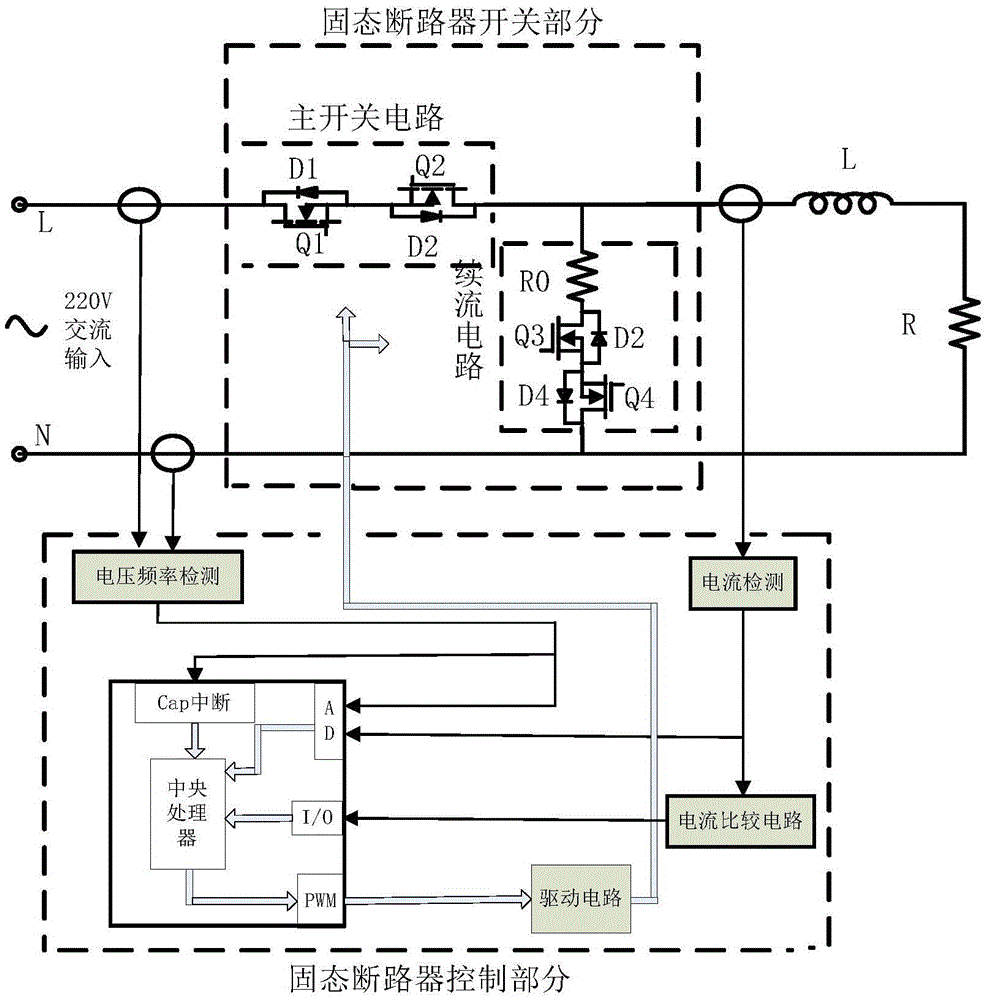
[0030] Referring to Fig. 1, the present invention provides a solid-state circuit breaker, which consists of three parts: a main switch circuit, a freewheeling circuit and a control system. The main switch circuit is composed of two MOS transistors Q1 and Q2 in reverse series. D1 and D2 in the main switch circuit are the parasitic diodes of Q1 and Q2 respectively. The drain of Q1 is connected to the input terminal L of the AC power supply; the freewheeling circuit is composed of Q3 It is composed of two MOS tubes in reverse series with Q4, D3 and D4 are the parasitic diodes of Q3 and Q4 respectively, the drain of Q3 in the freewheeling circuit is connected to the drain of Q2, and Q4 is connected to the input terminal N of the AC power supply; the control The system consists of main circuit current detection circuit, input...


PUM


Abstract

The invention relates to a current-limiting solid-state circuit breaker capable of actively suppressing overvoltage and a control method thereof. The circuit structure of the device is shown in a dotted frame in figure and comprises a master switching circuit, a follow current circuit and a control system, wherein the master switching circuit comprises a Q1 and a Q2, the follow current circuit comprises a Q3, a Q4 and a Q5, the master switching circuit is formed by reversely connecting two field effect transistors (MOSFET, MOS transistors) Q1 and Q2, an output end of the master switching circuit is connected with one end of the follow current circuit, the control system detects the input voltage of the solid-state circuit breaker and the current of the master switching circuit and controls the MOS transistors of the master switching circuit and the follow current circuit according to the input voltage and the current, the control system takes protective measure when the current of a main loop is detected to exceed a rated value or a current limiting value, the Q3 or the Q4 of a follow current branch is firstly conducted according to the directions of the current and the input voltage, the switching circuit is then cut off, higher voltage (Ldi / dt) caused by a stray inductor L in a power supply circuit during switching off the Q1 and the Q2 is prevented from being applied to the two ends of the MOS transistors of the master switching circuit, and the voltage stress during switching off the Q1 and the Q2 can be greatly reduced. Except for actively preventing overvoltage, compared with other solid-state circuit breaker, the current-limiting solid-state circuit breaker has the advantages that the MOSFET switching tubes are adopted, the structure is simple, the current-limiting solid-state circuit breaker is convenient to drive and easy to expand capacity in parallel, and the conduction loss is reduced.

Description

technical field [0001] The invention belongs to the technical field of power system fault protection, in particular to a topology of a current-limiting solid-state circuit breaker for actively suppressing overvoltage and a control method thereof. Background technique [0002] As an important link in the transmission line of the power grid, the circuit breaker is an important control and protection device, and its performance directly affects the normal operation of the power grid. It is stable and has a strong load capacity, but when the load is disconnected, an arc is often generated, the contacts are easily burned, and the breaking time is long, which is difficult to meet the quick action requirements of some power users for fault current breaking. [0003] Compared with the traditional mechanical circuit breaker, the solid-state circuit breaker based on power electronic devices has the remarkable structural features of no contact, no need for arc extinguishing and other m...

Claims


Application Information

Patent Timeline
IPC IPC(8): H02H3/093H02H9/02
Inventor 卢其威高志宣滕尚甫王聪程红邹甲雷婷
Owner CHINA UNIV OF MINING & TECH (BEIJING)
Learn More