Novel DC solid-state circuit breaker with self-adapt current limiting capability and the control method thereof

a solid-state circuit and self-adapting technology, applied in the direction of emergency protective circuit arrangements, emergency protection arrangements for limiting excess voltage/current, etc., can solve the problems of difficult arc extinguishing of dc faults, uncontrolled rectification methods, and endangering system operation security, so as to limit the dc fault current and propagate quickly

Active Publication Date: 2021-07-22
TIANJIN UNIV
View PDF0 Cites 7 Cited by
  • Summary
  • Abstract
  • Description
  • Claims
  • Application Information

AI Technical Summary

Benefits of technology

[0006]In view of the quick propagation speed and large damage of the DC fault in the flexible DC grid, the present invention provides a DC solid-state circuit breaker with self-adapt fault current limiting capability and the control method thereof. The proposed SSCB can limit the DC fault current quickly and automatically before the tripping signal from the protection is received. In addition, the negative influences of the fault current limiting reactor are avoided.

Problems solved by technology

However, all the flexible DC systems based on the above converters must confront a severe challenge: after DC faults, the fault current rises sharply, and the DC voltage drops rapidly, which seriously endangers the operation security of the system.
Even if the converter station is quickly blocked, the AC-side source will still feed the fault current to the fault point through the freewheeling diodes of the converter in an uncontrolled rectification manner.
It means that the DC fault current in the flexible DC system has no natural zero-crossing point, so the arc extinguishing of the DC fault is very difficult.
The improved converter with self-clearing capability will lead to a short power outage of the whole system.
It means the MMC will be blocked within several milliseconds or even several hundred microseconds due to IGBT self-protection, leading to the failure of the healthy network ride-through.
While the existing protection technologies can still not detect and locate the DC fault such quickly, especially, when the acting reliability is also required.
Moreover, the performance reliability of protection is directly related to a judgment time window, but it is very difficult to distinguish a fault from a disturbance within the judgment time window of hundreds of microseconds or milliseconds.
However, for the fault current limiting function, a high-frequency on-and-off control will be applied on the controllable switching devices, which is very detrimental to their service life.
In addition, this kind of current limiting characteristic is mainly resistive current limiting.
Actually, it is not very ideal to limit the rise rate of the current by resistive current limiting during the initial stage of the DC fault.
After DC faults, the rapid rise of the fault current and the rapid drop of the DC voltage can be limited by the reactors, namely, the propagation speed of the fault is slowed.
However, lots of reactors directly installed in the DC system are very disadvantageous to the transient response speed, and even the operation stability of the system, especially during the power flow shifting.
In addition, due to the freewheeling current of the reactors, the fault current clearing time after the DCCB being tripped will be prolonged drastically.
This is disadvantageous to the quick removal of the fault and then the quick recovery of the healthy remanent network.
Moreover, the arrester capacity of the DCCB must be larger under this condition, because it needs to dissipate the additional fault energy of the DC reactor.

Method used


Image

  • Novel DC solid-state circuit breaker with self-adapt current limiting capability and the control method thereof
  • Novel DC solid-state circuit breaker with self-adapt current limiting capability and the control method thereof
  • Novel DC solid-state circuit breaker with self-adapt current limiting capability and the control method thereof

Examples


first embodiment

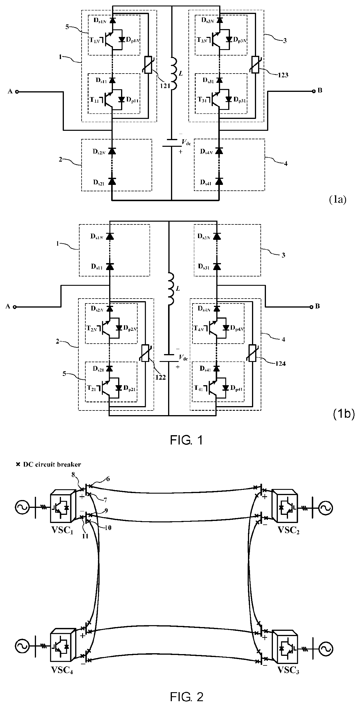
[0029]As shown in FIG. 1, FIG. 1a) shows the topology of the DC SSCB with self-adapt fault current limiting capability according to the present invention. The topology includes a H-bridge circuit consisting of the first bridge arm 1, the second bridge arm 2, the third bridge arm 3 and the fourth bridge arm 4, wherein the first bridge arm 1 and the second bridge arm 2 are connected in series, the third bridge arm 3 and the fourth bridge arm 4 are connected in series, and the series branch formed by the first bridge arm 1 and the second bridge arm 2 is connected in parallel to the series branch formed by the third bridge arm 3 and the fourth bridge arm 4. The specific topology of the bridge arms will be described below in detail.

[0030]The first bridge arm 1 and the third bridge arm 3 are named as the unidirectional breakable bridge arms, and each of them is formed by connecting N unidirectional breakable modules 5 in series and then connecting them to the arrester (121 or 123) in para...

second embodiment

[0031]As shown in FIG. 1, FIG. 1b) shows the topology of the DC SSCB with self-adapt fault current limiting capability according to the present invention. The topology includes a H-bridge circuit consisting of the first bridge arm 1, the second bridge arm 2, the third bridge arm 3 and the fourth bridge arm 4, wherein the first bridge arm 1 and the second bridge arm 2 are connected in series, the third bridge arm 3 and the fourth bridge arm 4 are connected in series, and the series branch formed by the first bridge arm 1 and the second bridge arm 2 is connected in parallel to the series branch formed by the third bridge arm 3 and the fourth bridge arm 4. The specific topology of the bridge arms will be described below in detail.

[0032]Each of the first bridge arm 1 and the third bridge arm 3 is formed by connecting N diodes (Ds11-Ds1N and Ds31-Ds3N) in series. Each of the second bridge arm 2 and the fourth bridge arm 4 is formed by connecting N unidirectional breakable modules 5 in se...


PUM


Abstract

The present invention discloses a DC solid-state circuit breaker with self-adapt fault current limiting capability. The topology of the DC solid-state circuit breaker is a H-bridge circuit consisting of two unidirectional breakable bridge arms and two series-connected diode bridge arms, wherein the two unidirectional breakable bridge arms are connected in series to the two series-connected diode bridge arms in a same direction to form two series branches, respectively; the series branches are connected in parallel; a series branch formed by a DC reactor L and a DC biased power supply is connected to the PCC between the two unidirectional breakable bridge arms and the PCC between the two series-connected diode bridge arms; the DC line is connected to the two PCCs, respectively.

Description

TECHNICAL FIELD[0001]The present invention relates to the field of DC power transmission networks / power distribution networks / microgrids, and in particular to a novel DC solid-state circuit breaker (SSCB).BACKGROUND OF THE PRESENT INVENTION[0002]In present, the typical converters in the flexible DC system mainly include two-level voltage source converters (hereinafter referred to as VSCs), three-level VSCs and modular multilevel converters (hereinafter referred to as MMCs). However, all the flexible DC systems based on the above converters must confront a severe challenge: after DC faults, the fault current rises sharply, and the DC voltage drops rapidly, which seriously endangers the operation security of the system. Even if the converter station is quickly blocked, the AC-side source will still feed the fault current to the fault point through the freewheeling diodes of the converter in an uncontrolled rectification manner. It means that the DC fault current in the flexible DC sys...

Claims


Application Information

Patent Timeline
Patent Type & Authority Applications(United States)
IPC IPC(8): H02H3/087H02H1/06H02H3/02
CPCH02H3/087H02H3/021H02H1/06H02H7/268H02H7/28H02H9/02H02H3/025
Inventor LI, BINHE, JIAWEI
Owner TIANJIN UNIV
Why Eureka
Try Eureka