Cathode short MOS-controlled thyristor-based DC solid state circuit breaker

A solid-state circuit breaker and thyristor technology, which is applied in the electronic field, can solve problems such as complex drive circuits, poor di/dt capability of thyristors, and long commutation time of short-circuit currents, and achieve simple drive control, fast response speed, and high reliability. Effect

Active Publication Date: 2018-01-16
UNIV OF ELECTRONICS SCI & TECH OF CHINA
View PDF5 Cites 7 Cited by
  • Summary
  • Abstract
  • Description
  • Claims
  • Application Information

AI Technical Summary

Problems solved by technology

However, due to the current concentration effect during the turn-on process, the di / dt capability of the thyristor is poor
The use of thyristors in SSCBs based on resonant commutation technology results in longer commutation times for short-circuit currents flowing through the load, resulting in longer response times for circuit breakers
In addition, compared with voltage-controlled devices, the drive and protection of flow-controlled devices are more complex
Gate Controlled Thyristor ( M OS- C onrolled T hyristor, MCT) has low-resistance characteristics similar to thyristors, and has high di / dt capability and voltage control characteristics, but the device needs gate control signals of different signs during the switching process, resulting in more complex drive circuits (Temple V A K.MOScontrolled thyristors (MCT's)[C].Electron Devices Meeting,1984International.IEEE,1984:282-285.)
Devices based on wide bandgap semiconductor materials such as SiC and GaN have low conduction power consumption, but their applications are limited by device reliability and cost (Shenai K, Dudley M, Davis RF. Current status and emerging trends in wide bandgap (WBG)semiconductor powerswitching devices[J].ECS Journal of Solid State Science and Technology,2013,2(8):N3055-N3063.)

Method used


Image

  • Cathode short MOS-controlled thyristor-based DC solid state circuit breaker
  • Cathode short MOS-controlled thyristor-based DC solid state circuit breaker
  • Cathode short MOS-controlled thyristor-based DC solid state circuit breaker

Examples


Embodiment Construction

[0017] Below in conjunction with specific accompanying drawing, the present invention is described in further detail:

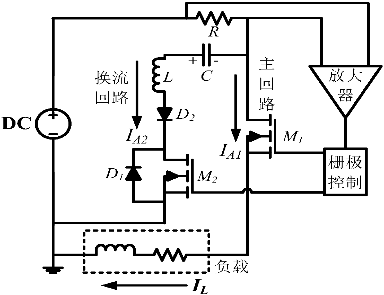
[0018] Such as figure 1 As shown, it is a schematic circuit diagram of the SSCB in the present invention, including a main circuit, a commutation circuit, a current detection unit and a grid control unit, and the main circuit includes a DC power supply, a first CS-MCT (M 1 ) and load. The basic working principle of the circuit is:

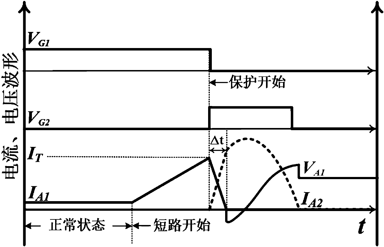
[0019] Such as figure 2 As shown, when the system is in normal working condition, M 1 In the conduction state, M 2 In the blocking state, the current only flows through the main circuit, and the capacitor C is pre-charged with a certain amount of energy, and its voltage polarity is as follows: figure 1 shown. When a short circuit occurs, the current on the main circuit (I A1 ) rises rapidly, and its rate of rise depends on the relative size of the DC power supply voltage and the parasitic inductance of the power supply sys...


PUM


Abstract

The present invention belongs to the electronic technology field, in particular relates to a cathode short MOS-controlled thyristor-based DC solid state circuit breaker. The cathode short MOS-controlled thyristor-based DC solid state circuit breaker of the present invention mainly comprises a main loop composed of a DC power supply, a cathode short MOS-controlled thyristor (CS-MCT) (M1) and a load, a current commutation loop composed of the DC power supply, a capacitor C, an inductor L, a CS-MCT(M2) and diodes (D1 and D2), a current detection unit composed of a current sampling resistor R andan amplifier and a grid control unit, and is characterized by adopting the CS-MCT having the low conduction resistance and high di / dt capability as a switching tube, combining the current detection unit and the grid control unit to realize the short circuit current sampling and the control signal feedback, and utilizing the shunting action of the current commutation loop to interrupt a short circuit current rapidly. Compared with a conventional solid state circuit breaker, the CS-MCT-based DC solid state circuit breaker of the present invention has the advantages of being low in power consumption and fast in response speed.

Description

technical field [0001] The invention belongs to the field of electronic technology, and in particular relates to a DC solid-state circuit breaker based on a cathode short-circuit gate-controlled thyristor. Background technique [0002] With the coordinated development of economy and technology, society's demand for various types of energy is increasing. As the "blood" of today's information age, electric energy provides power for the progress of economy and technological level. Among them, renewable clean energy represented by photovoltaics and wind power has attracted much attention due to its relatively small environmental cost. In order to make fuller and more flexible use of the above-mentioned clean energy to meet the demand of load growth, reduce environmental pollution, improve the comprehensive utilization efficiency of energy and the reliability of power supply, based on the distributed generation system ( D distributed G generation S system, DGS) microgrid came...

Claims


Application Information

Patent Timeline
Patent Type & Authority Applications(China)
IPC IPC(8): H03K17/0812H03K17/72
Inventor 陈万军陶宏刘亚伟刘承芳刘杰
Owner UNIV OF ELECTRONICS SCI & TECH OF CHINA
Why Eureka
Try Eureka