Power managing method and electronic system applying the power managing method

A management method and electronic system technology, applied in power management, TV system components, data processing power supply, etc., can solve problems such as increased battery impedance, increased total power impedance, and difficulty in reducing total power impedance

Inactive Publication Date: 2016-04-27
MEDIATEK INC
View PDF3 Cites 2 Cited by
  • Summary
  • Abstract
  • Description
  • Claims
  • Application Information

AI Technical Summary

Problems solved by technology

However, it is difficult to reduce the total power impedance
In addition, if the battery has been used for a long time, the battery impedance will increase, making the total power impedance correspondingly higher and making the above problem worse

Method used


Image

  • Power managing method and electronic system applying the power managing method
  • Power managing method and electronic system applying the power managing method
  • Power managing method and electronic system applying the power managing method

Examples


Embodiment Construction

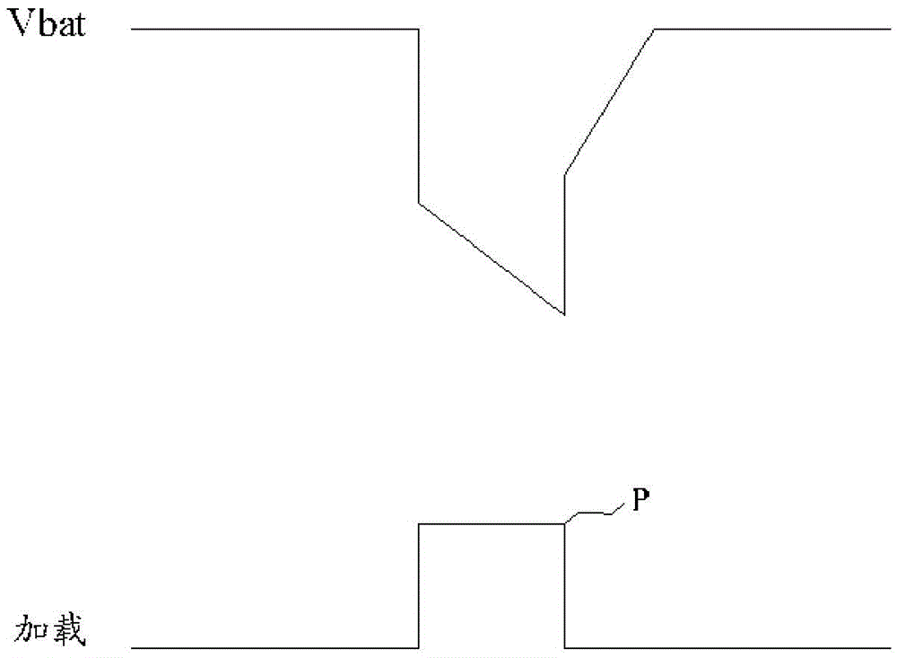
[0025] The power management mechanism provided by the present invention is described as follows. Power management mechanisms include Figure 4-Figure 6 Describes the passive mode as well as Figure 7 , Figure 8 Describes the active mode. Passive mode and active mode can be used simultaneously or independently.

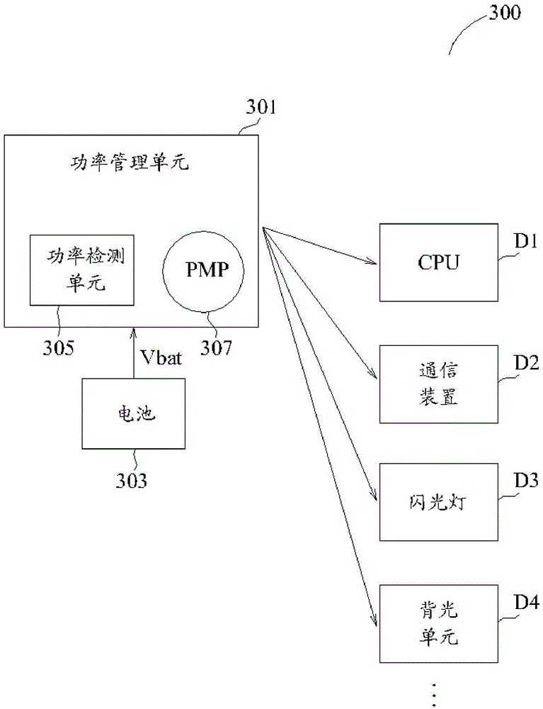
[0026] image 3 is a block diagram of an electronic system described according to an embodiment of the present invention. Figure 4 and Figure 5 is described according to the embodiment of the present invention image 3 Schematic diagram of the operation of the electronic system. Please also refer to image 3 / Figure 4 or image 3 / Figure 5 , to understand the content of the present invention more clearly.

[0027] Such as image 3 As shown, the electronic system 300 includes a power management unit 301 , a battery 303 , and a plurality of electronic devices D1 , D2 , D3 and D4 . The power management unit 301 detects the battery voltage Vbat of the ...


PUM


Abstract

An electronic system (300) comprising: a battery (303); at least one electronic device; and a power managing unit (301), arranged for detecting a battery voltage of the battery (303), and arranged for limiting at least one performance of the at least one electronic device if the battery voltage is not higher than a first low threshold voltage.

Description

[0001] cross reference [0002] This application claims priority to US Provisional Patent Application Serial No. 61 / 981,294, filed April 18, 2014. The aforementioned US Provisional Patent Application is hereby incorporated by reference. technical field [0003] The invention relates to a power management method and an electronic system applying the power management method. In particular, the present invention relates to a power management method for avoiding a sudden drop in battery voltage and an electronic system applying the power management method. Background technique [0004] Traditionally, portable electronic systems (eg, mobile phones, laptops, or tablets) contain batteries for power. However, if the battery's cell voltage suddenly drops due to a load spike, many problems can arise. [0005] figure 1 is a schematic diagram describing the voltage drop problem of a conventional battery. Such as figure 1 As shown, due to the appearance of the peak load P, the b...

Claims


Application Information

Patent Timeline
Patent Type & Authority Applications(China)
IPC IPC(8): G06F1/26
CPCG06F1/3206G06F1/329H04N23/651G06F1/324G06F1/3278G06F1/3287H04W52/0277H02J7/0063G06F1/3212Y02D10/00Y02D30/70H02J7/0048H02J7/007182G06F1/3234G06F1/3296G06F1/305G06F1/3275
Inventor 杨仁杰罗永圣周楷勋林冠甫
Owner MEDIATEK INC
Why Eureka
Try Eureka