Cleaning machine structure

A cleaning machine and machine body technology, which is applied to cleaning machines, carpet sweepers, carpet cleaning, etc., can solve problems such as deficiencies, and achieve the effects of reasonable structure, good cleaning effect, and good stability

Active Publication Date: 2016-05-04
TECHTRONIC CORDLESS GP
View PDF5 Cites 18 Cited by
  • Summary
  • Abstract
  • Description
  • Claims
  • Application Information

AI Technical Summary

Problems solved by technology

Although the carpet cleaners in the prior art can realize the cleaning function, they are still lacking in the stability of the working process, the strengthening of the cleaning effect, and the intelligence and convenience of operation control.

Method used


Image

  • Cleaning machine structure
  • Cleaning machine structure
  • Cleaning machine structure

Examples


Embodiment 1

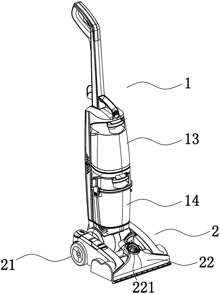
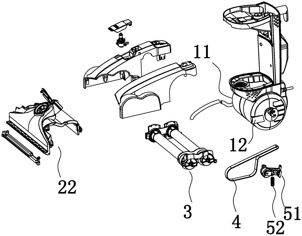
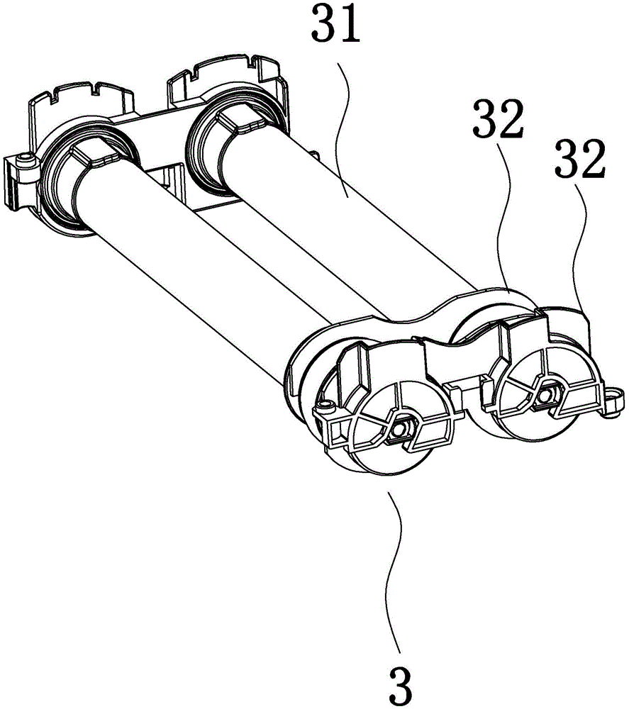
[0026] Example 1: Such as Figure 1 to Figure 6 In the illustrated embodiment, a cleaning machine structure includes a main body 1, a floor mop 2, a clean water bucket 13 and a recovery bucket 14 are provided on the main body, a sewage suction nozzle 22, a pair of ground wheels are provided on the floor mop, and the main body The lower end of the body is rotatably connected to the ground mop. The ground mop is provided with a double roller brush structure 3, which includes two parallel roller brush shafts 31. The roller brush shafts are provided with bristles and the lower part of the main body There is a motor shell 12, a power motor is arranged in the motor shell, and an active pulley driven by the power motor is set on the ground mop. A drive belt 4 bypasses the active pulley and two roller brush shafts. The drive belt is closed end and end A belt loop is formed, the inner loop surface of the belt loop is an inner belt surface, the outer loop surface of the belt loop is an o...

Embodiment 2

[0033] Example 2: The basic structure and implementation of the present invention are the same as Example 1, the difference is that Figure 7 , Figure 8 As shown in the above, the barrel body is provided with a baffle 145, a vertical pivot arm 146 rotatably connected with the baffle is provided on the baffle, a pressure block 147 for contact with the float is provided at the lower end of the pivot arm, and the upper end of the baffle is provided A locking rod 148 that can move to the float arm and a compression spring 149 that abuts the lock rod against the upper end of the swing arm, and the upper end of the swing arm is provided with a contact portion against one end of the lock rod. When the water surface shakes violently, which makes the float swing larger, the float will contact the pressure block to push the rotating arm to rotate. The upper end of the rotating arm acts on the locking rod, and the locking rod is pushed out to the float arm to lock the rod end. The part ab...


PUM


Abstract

The invention discloses a cleaning machine structure. The cleaning machine structure comprises a main machine body, a floor mop, a clean water bucket, a recovery bucket and a sewage suction nozzle. The lower end of the main machine body is rotatably connected with the floor mop, the floor mop is provided with a double-rolling-brush structure, the double-rolling-brush structure comprises two parallel rolling brush shafts, each rolling brush shaft is provided with brush bristles, a motor shell is arranged on the lower portion of the main machine body, a power motor is arranged in the motor shell, the floor mop is provided with a driving pulley, a driving belt bypasses the driving pulley and the two rolling brush shafts, the head and the tail of the driving belt are closed for forming a belt ring, and the inner belt surface is in contact with the driving pulley and the two rolling brush shafts. The cleaning machine structure has the advantages that a floor can be effectively cleaned, stability is good in the working process, and the cleaning effect is excellent; the cleaning machine structure is provided with an intelligent adjusting structure, working state switching of rolling brushes can be achieved automatically according to the situation whether a user needs to clean the floor or not, no extra operation is needed, and convenience, rapidness and high efficiency are achieved; the cleaning machine structure is provided with a water-gas separation structure and an auto-adaptation structure, so that sewage can be prevented from leaking out.

Description

Technical field [0001] The present invention belongs to the technical field of carpet cleaning machines, and particularly relates to a cleaning machine structure. Background technique [0002] As a cleaning appliance, carpet (floor) cleaning machine has been widely used in homes, hotels, etc. The main functions of the cleaning machine are cleaning, floor cleaning, recycling, etc. Correspondingly, the carpet cleaning machine should also have a water supply component, a floor brush component, and a sewage recovery component. These components have different functions but are closely related. Although the carpet cleaning machine of the prior art can realize the cleaning function, it still lacks in the stability of the working process, the enhancement of the cleaning effect, and the intelligence and convenience of operation control. Summary of the invention [0003] In order to overcome the shortcomings in the prior art, the invention provides a cleaning machine with reasonable struct...

Claims


Application Information

Patent Timeline
Patent Type & Authority Applications(China)
IPC IPC(8): A47L11/282A47L11/33A47L11/40
CPCA47L11/282A47L11/33A47L11/4016
Inventor 黄家安
Owner TECHTRONIC CORDLESS GP
Why Eureka
Try Eureka