Positive and negative pressure coupling foam jetting device

An injection device, positive and negative pressure technology, applied in the field of foam fire extinguishing, can solve the problems of incomplete foaming, good fire extinguishing effect, poor foam stability, etc., and achieve the effect of saving gas consumption, low gas consumption, and good foam performance

Active Publication Date: 2016-05-04
CHINA PETROLEUM & CHEM CORP +1
View PDF10 Cites 18 Cited by
  • Summary
  • Abstract
  • Description
  • Claims
  • Application Information

AI Technical Summary

Problems solved by technology

[0002] At present, most of the fire extinguishing in Class B fire places uses the air-breathing foam fire extinguishing system. The foam fire extinguishing system belongs to the negative pressure foam system. The fire extinguishing effect is not high, especially when the foam is sprayed at a large flow rate, the sprayed foam cannot be completely foamed by air suction, resulting in poor foam effect; before adopting the positive pressure foam fire extinguishing system, high-pressure gas is forced into the foam mixture for forced Foaming, the formed foam is stable, the bubbles are uniform, and the fire extinguishing effect is good
For the positive pressure foam system, when the flow rate of the foam system increases, the amount of gas consumed also increases accordingly. Affected by the gas supply rate, the flow rate of the positive pressure foam system is often limited to a certain extent, and it cannot achieve large For flow injection, the flow rate of the general positive pressure foam system is 3000-5000L / min, while the foam flow rate required for large oil tank fire extinguishing is often above 8000-10000L / min. The positive pressure foam system cannot be applied to large-scale fire fighting. Limits the range of applications for positive pressure foam systems

Method used


Image

  • Positive and negative pressure coupling foam jetting device
  • Positive and negative pressure coupling foam jetting device

Examples


Embodiment Construction

[0019] Below in conjunction with accompanying drawing and specific embodiment the present invention is described in further detail:

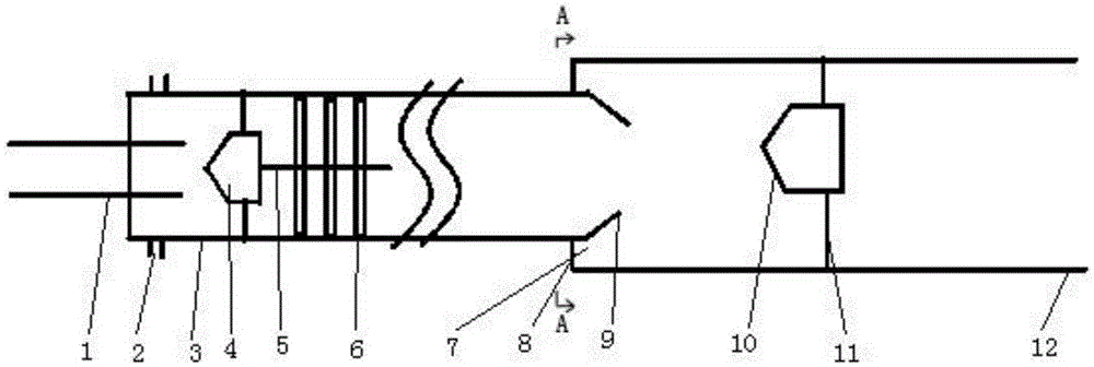
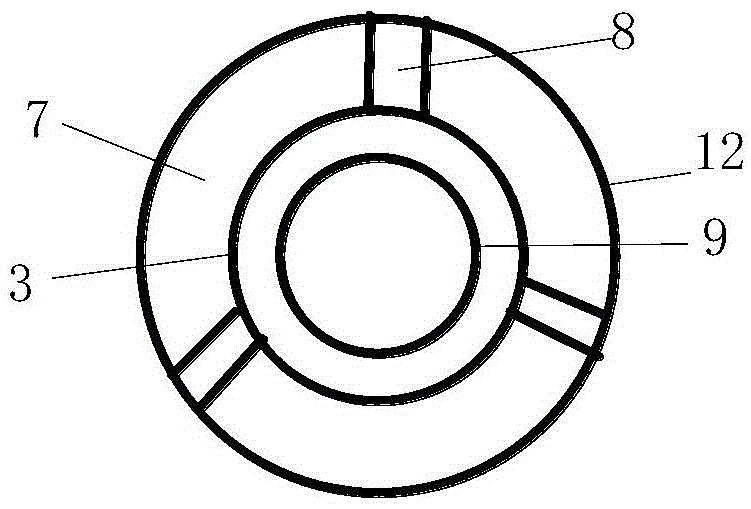
[0020] Positive and negative pressure coupling foam injection device, including liquid suction pipe 1, gas injection hole 2, gas-liquid mixing pipe 3, primary spoiler 4, secondary spoiler 6, positive pressure foam injection port 9, foam injection pipe 12 and three times Spoiler 10. in,

[0021] The diameter of the gas-liquid mixing pipe 3 is smaller than that of the foam injection pipe 12 .

[0022] The liquid suction pipe 1 is connected to the rear end of the gas-liquid mixing pipe 3; a foam mixed liquid fire pump is arranged behind the liquid suction pipe 1 for injecting the foam mixed liquid into the liquid suction pipe 1.

[0023] The gas injection hole 2 is arranged on the circumferential side wall of the rear part of the gas-liquid mixing tube 3 . This gas injection hole 2 can have one, also can have a plurality of. When there are mult...


PUM


Abstract

The invention discloses a positive and negative pressure coupling foam jetting device. The positive and negative pressure coupling foam jetting device comprises a pipette, gas injection holes, a gas-liquid mixing pipe, a primary turbulator, a secondary turbulator, a positive pressure foam jet orifice, a foam jetting pipe and a third turbulator, wherein the diameter of the gas-liquid mixing pipe is smaller than that of the foam jetting pipe; the pipette is connected to the rear end of the gas-liquid mixing pipe; the gas injection holes are formed in the circumferential side wall of the rear portion of the gas-liquid mixing pipe; the primary turbulator and the secondary turbulator are installed in the gas-liquid mixing pipe; the positive pressure foam jet orifice is connected to the front end of the gas-liquid mixing pipe and forwards extends into the foam jetting pipe; gas sucking holes are evenly formed in the rear end of the foam jetting pipe; the third turbulator is installed inside the foam jetting pipe. Large-flow jetting of positive pressure type foam with low gas consumption is achieved, and the gas consumption of a positive pressure type foam system is saved; a foam mixture has the good foam performance under the large-flow jetting, and the foam performance of a negative pressure type foam system is improved.

Description

technical field [0001] The invention belongs to the field of foam fire extinguishing, and in particular relates to a positive and negative pressure coupling foam injection device, which is suitable for oil depots, gas stations, petrochemical enterprises and other places. Background technique [0002] At present, most of the fire extinguishing in Class B fire places uses the air-breathing foam fire extinguishing system. The foam fire extinguishing system belongs to the negative pressure foam system. The fire extinguishing effect is not high, especially when the foam is sprayed at a large flow rate, the sprayed foam cannot be completely foamed by air suction, resulting in poor foam effect; before adopting the positive pressure foam fire extinguishing system, high-pressure gas is forced into the foam mixture for forced Foaming, the formed foam is stable, the bubbles are uniform, and the fire extinguishing effect is good. For the positive pressure foam system, when the flow rat...

Claims


Application Information

Patent Timeline
Patent Type & Authority Applications(China)
IPC IPC(8): A62C31/12A62C3/06
CPCA62C3/06A62C31/12A62C5/02A62C99/0036
Inventor 牟小冬郎需庆吴京峰谈龙妹尚祖政
Owner CHINA PETROLEUM & CHEM CORP
Why Eureka
Try Eureka