Position detection system

A detection system and detection device technology, used in length measuring devices, metal processing equipment, metal rolling, etc., can solve the problems of shutdown, low detection accuracy, no signal output from limit switches, etc., and achieve detection position preparation and precision control. , the effect of improving the coefficient of precision

Inactive Publication Date: 2016-05-04
SHAANXI JOIN CREATE SCI & TECH
View PDF0 Cites 0 Cited by
  • Summary
  • Abstract
  • Description
  • Claims
  • Application Information

AI Technical Summary

Problems solved by technology

For example, the automatic detection and control of the translational and lifting positions of the coiling rolls of the coiler and the walking beam of the heating furnace in the hot rolling mill. Considering the running condition and running trend of the equipment, when the walking beam is translated and lifted by vibration and jitter, the limit switch has no signal output, which is very likely to cause production stoppage

Method used


Image

  • Position detection system

Examples


Embodiment 1

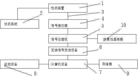
[0012] Such as figure 1 As shown, the present invention: a position detection system, including a detection device 1, the detection device 1 is connected to the detection system 2, the detection device 1 is connected to the signal receiver 4 through the optical waveguide 3, and the signal receiver 4 is connected to the signal processing through the optical waveguide 3 The board 5 and the signal processing board 5 are connected to the computer equipment 7 through the wireless signal sending equipment 6, and the computer equipment 7 is provided with a monitoring equipment 8. A storage device 9 is provided in the computer device 7 . The signal processing board 5 is provided with an anti-vibration crystal oscillator 10 . The detection position is prepared, the precision control is precise, and the precision coefficient of the system is improved.


PUM


Abstract

The invention discloses a position detection system. The position detection system comprises a detection device. The detection device is connected with a sensing system and connected with a signal receiver through a light wave wire. The signal receiver is connected with a signal processing panel through a light wave wire. The signal processing panel is connected with computer equipment through wireless signal sending equipment, and the computer equipment is provided with monitoring equipment. The position detection system has the advantages that position detection is accurate, the precision is well controlled, and the accuracy coefficient of the system is improved.

Description

technical field [0001] The invention relates to a position detection system, which belongs to the field of alarm detection. Background technique [0002] In the field of metallurgy, it is necessary to accurately position various running mechanisms to realize semi-automatic or fully automated production in the factory, which can save labor and accurately position mechanical equipment to improve the processing quality of products. For example, the automatic detection and control of the translational and lifting positions of the coiling rolls of the coiler and the walking beam of the heating furnace in the hot rolling mill. Considering the running condition and running trend of the equipment, when the walking beam is translated and lifted by vibration and jitter, the limit switch has no signal output, which is very likely to cause production stoppage. Therefore, a new technology needs to be sought to solve this problem. Contents of the invention [0003] The purpose of the ...

Claims


Application Information

Patent Timeline
Patent Type & Authority Applications(China)
IPC IPC(8): B21B38/00
Inventor 不公告发明人
Owner SHAANXI JOIN CREATE SCI & TECH
Why Eureka
Try Eureka