A constant force grinding tool for grinding the mold surface of an automobile panel

A technology for automobile cover parts and mold profiles, which is applied to grinding tools, grinding devices, grinding machine tools, etc., can solve the problems of increasing the mold manufacturing cycle, reducing the mold manufacturing efficiency, and long grinding time, shortening the manufacturing cycle and saving manpower. , the effect of high grinding speed

Inactive Publication Date: 2017-10-20
HARBIN UNIV OF SCI & TECH
View PDF6 Cites 0 Cited by
  • Summary
  • Abstract
  • Description
  • Claims
  • Application Information

AI Technical Summary

Problems solved by technology

[0004] In order to solve the problems that the existing large-scale automobile panel mold is polished after CNC milling, the grinding time is long, the stability is poor, the manufacturing cycle of the mold is increased, and the manufacturing efficiency of the mold is reduced, and a kind of automobile panel mold is proposed. Constant Force Grinding Tools for Profile Grinding

Method used


Image

  • A constant force grinding tool for grinding the mold surface of an automobile panel
  • A constant force grinding tool for grinding the mold surface of an automobile panel
  • A constant force grinding tool for grinding the mold surface of an automobile panel

Examples


specific Embodiment approach 1

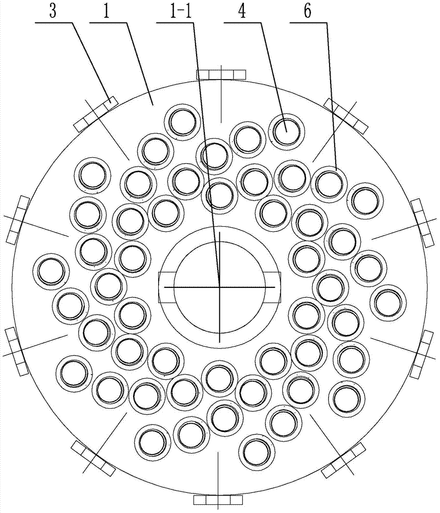
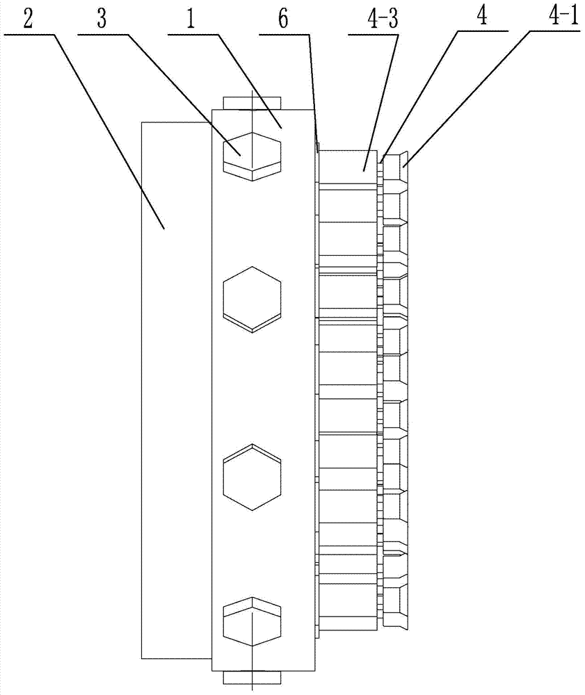
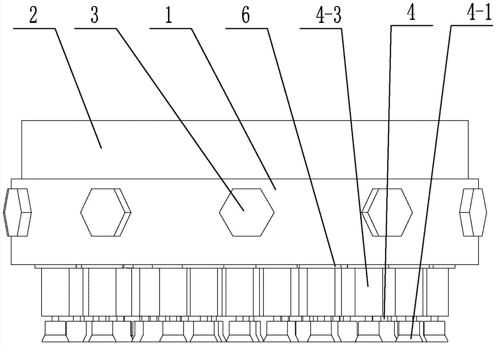
[0022] Specific implementation mode one: combine Figure 1 to Figure 11 Explain that a constant force grinding tool for grinding the mold surface of an automobile cover part according to this embodiment includes an upper base body 1, a lower base body 2, a plurality of connecting bolts 3, a plurality of constant force springs 5 ​​and a plurality of sets of telescopic rods 4, Both the upper base 1 and the lower base 2 are disc-shaped, and the lower end surface of the upper base 1 is provided with a groove 1-1, and the groove 1-1 is set on the outside of the lower base 2, and the upper base 1 is connected by a plurality of connecting bolts 3 It is fixedly connected with the lower substrate 2, the middle part of the upper substrate 1 is provided with an upper connection through hole 1-2, the middle part of the lower substrate 2 is provided with a lower connection through hole 2-1, and the upper end surface of the upper substrate 1 is evenly arranged with multiple sets of limiters....

specific Embodiment approach 2

[0024] Specific implementation mode two: combination Figure 9 and Figure 11 Note that the constant force spring 5 in this embodiment includes two supporting springs 5-1 and a connecting frame 5-2, the two supporting springs 5-1 are connected through the connecting frame 5-2, and the supporting spring 5-1 is horizontally arranged on the column One side of body 4-3 lower end surface, the outside of the lower end surface of cylinder body 4-3 at the two ends of every group of expansion rod 4 is equipped with a supporting spring 5-1 by connecting frame 5-2 horizontal clamping. Other compositions and connection methods are the same as those in Embodiment 1.

[0025] This design ensures that each telescopic rod 4 is balanced in force on the premise of providing sufficient support for the telescopic rod 4 .

specific Embodiment approach 3

[0026] Specific implementation mode three: combination Figure 4 and Figure 5 Note that each telescopic rod 4 in this embodiment further includes a circlip 4-2, and the circlip 4-2 is arranged between the upper end surface of the cylinder 4-3 and the lower end surface of the grinding head 4-1. Other compositions and connection methods are the same as those in the second embodiment.

[0027] The jumper 4-2 is designed in this way to ensure that the cylinder 4-3 is stably connected with the grinding head 4-1, the telescopic rod 4 is stretchable and stable, and the grinding head 4-3 is stable in rotation.


PUM


Abstract

The invention discloses a constant-force grinding tool for grinding a molded surface of a vehicle covering part mold. The invention relates to a grinding tool, in particular to the constant-force grinding tool for grinding the molded surface of the vehicle covering part mold. The invention aims to solve the problems of long polishing time and weak stability during polishing of a traditional large vehicle covering part mold after numerical control milling. The constant-force grinding tool for grinding the molded surface of the vehicle covering part mold comprises an upper basal body, a lower basal body, multiple connecting bolts, multiple constant-force springs and multiple sets of extension rods; the upper basal body is fixedly connected with the lower basal body through multiple connecting bolts; multiple sets of limiting through holes are uniformly distributed in the upper end surface of the upper basal body; multiple sets of limiting blind holes are uniformly distributed in the upper end surface of the lower basal body; each extension rod includes a grinding head and a column body; the upper end surfaces of the column bodies are rotationally connected with the grinding heads; the column bodies are slidingly connected with the limiting through holes and the limiting blind holes; and the constant-force springs are respectively arranged between two adjacent column bodies. The constant-force grinding tool is used for grinding the molded surface.

Description

technical field [0001] The invention relates to a grinding tool for grinding, in particular to a constant force grinding tool for grinding the mold surface of an automobile cover part. Background technique [0002] With the rapid development of the automobile industry, automobiles are developing towards customization, especially the appearance of automobiles. Automobile panels are mainly formed by pressing molds, so the production efficiency of the molds used for manufacturing is very important for the replacement of automobiles. [0003] After the large-scale automobile panel mold is milled by CNC, the texture of the tool track will be produced. This texture will reduce the surface finish of the automobile panel. Manual methods such as grinding with a small grinder not only waste manpower greatly, but also cause poor stability of the processed surface quality due to differences in the strength and experience of different workers. Sometimes after the CNC milling of a large...

Claims


Application Information

Patent Timeline
Patent Type & Authority Patents(China)
IPC IPC(8): B24B37/11B24B37/00B24B27/00B24B19/20
CPCB24B19/20B24B27/0092B24B37/00B24B37/11
Inventor 计伟施金奎刘献礼
Owner HARBIN UNIV OF SCI & TECH
Why Eureka
Try Eureka