Reconfigurable spherical parallel robot
A robot and parallel technology, applied in the direction of manipulators, program control manipulators, manufacturing tools, etc., can solve the problems that the flexibility of robots cannot be satisfied, and achieve the effect of compact structure and simple mechanism
- Summary
- Abstract
- Description
- Claims
- Application Information
AI Technical Summary
Problems solved by technology
Method used
Image
Examples
Embodiment 1
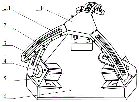
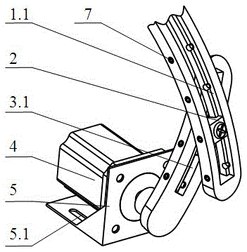
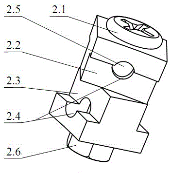
[0035] The reconfigurable spherical parallel robot in this embodiment is a six-degree-of-freedom configuration, including: a moving platform 1 , a driving branch chain, a fixed platform 6 and the like. The moving platform 1 and the fixed platform 6 are connected by three driving branch chains with the same structure, and the moving platform 1 and the arc rod 3 are connected through the combined slider 2, which can realize the sliding of the combined slider 2 on the moving platform 1 The track I1.1 slides on the sliding track II3.1 of the arc rod 3, and the fixed platform 6 and the motor bracket 5 are fixedly connected through the positioning hole 5.1.
[0036]The three driving branch chains are identical, including: a combined slider 2, an arc rod 3, a motor 4, a motor support 5 and a kinematic pair; there are four kinematic pairs of the driving branch chain, one of which is connected to the motor 4 and the rotating pair R between the arc rod 3, one is the moving pair P connec...
Embodiment 2
[0039] The reconfigurable spherical parallel robot of this embodiment is a three-degree-of-freedom configuration. The difference between this configuration and Embodiment 1 is that there are three kinematic pairs of the drive branch chain, which are connected to the arc rod The moving pair P between 3 and slider II 2.3 is locked, and only the arc rod 3 rotates around the motor shaft under the action of the driving force.
Embodiment 3
[0041] The reconfigurable spherical parallel robot in this embodiment is a three-degree-of-freedom configuration. The difference between this configuration and Embodiment 1 is that there are three kinematic pairs of the drive branch chain, which are connected to the combined slider. The moving pair P between the slider I 2.2 in 2 and the sliding track 1.1 on the moving platform 1 is locked, and only the arc-shaped rod 3 rotates around the motor shaft under the action of the driving force.
PUM
 Abstract
Description
Claims
Application Information
 - R&D
- Intellectual Property
- Life Sciences
- Materials
- Tech Scout
- Unparalleled Data Quality
- Higher Quality Content
- 60% Fewer Hallucinations
Browse by: Latest US Patents, China's latest patents, Technical Efficacy Thesaurus, Application Domain, Technology Topic, Popular Technical Reports.
© 2025 PatSnap. All rights reserved.Legal|Privacy policy|Modern Slavery Act Transparency Statement|Sitemap|About US| Contact US: help@patsnap.com


