Metal plasma source and application thereof

A plasma source and metal technology, applied in the field of ion source, can solve the problems of low beam density, difficulty in stable discharge, high ignition pressure and working pressure, etc., and achieve the effects of increasing electron concentration, reducing electron escape, and reducing working pressure

Inactive Publication Date: 2016-05-04
PEKING UNIV SHENZHEN GRADUATE SCHOOL
View PDF4 Cites 2 Cited by
  • Summary
  • Abstract
  • Description
  • Claims
  • Application Information

AI Technical Summary

Problems solved by technology

[0003] However, further studies have found that in a cylindrical metal plasma source, when the bar magnets used are arranged around the cylinder, there will be obvious magnetic flux leakage at the end of the metal plasma source, and the magnetic field lines will be inclined outward. , instead of forming an arched magnetic force line perpendicular to the magnetron target; this leads

Method used


Image

  • Metal plasma source and application thereof
  • Metal plasma source and application thereof
  • Metal plasma source and application thereof

Examples


Embodiment 1

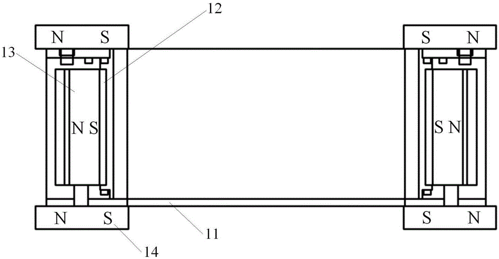
[0035] The metal plasma source of this example, such as figure 1As shown, it includes a housing 11 , a magnetron target 12 , a magnetic element 13 and a suppression magnetic element 14 . The casing 11 is in the shape of a hollow cylinder, and the magnetron target 12 is laid in the hollow inner cavity of the casing 11, and is not connected to the casing 11. The magnetic element 13 is laid between the magnetron target 12 and the casing 11, and suppresses the magnetic element 14 are mounted on both ends of the magnetic element 13 in pairs, and the magnetic element 14 is suppressed to have the same polarity as the ends of the magnetic element 13 . figure 1 Among them, N and S represent the N pole and S pole of the magnet respectively, and the suppression of the polarity of the magnetic element 14 and the end of the magnetic element 13 means that the direction of the N pole and the S pole of the suppression magnetic element 14 and the magnetic element 13 are the same, such as f...

Embodiment 2

[0044] The metal plasma source of this example is the same as that of Embodiment 1, except that the suppression magnetic element 44 is installed inside the casing 41, as Figure 4 shown. In addition, the suppressing magnetic element 44 of this example is a permanent magnet of FeCrCo permanent magnet alloy, with a strength of 50 mT, a length of 40 mm, and a width and a height of 5 mm. The rest, including the installation of the magnetron target 42, the magnetic element 43, etc., are the same as those in the first embodiment. Figure 4 N and S represent the N pole and S pole of the magnet, respectively.

[0045] When the metal plasma source of this example is in use, its additionally installed suppression magnetic element 44 can also reduce the escape of electrons, so that more electrons stay inside the metal plasma source, which can reduce working conditions and improve sputtering materials. ionization rate and target utilization.

Embodiment 3

[0047] This example is the same as the metal plasma source in Embodiment 1, except that an auxiliary ionization discharge device is added on the metal plasma source, such as Figure 5 As shown, in this example a microwave device 55 is added to the metal plasma source. The rest, including the installation of the housing 51 , the magnetron target 52 , the magnetic element 53 and the suppressing magnetic element 54 , are the same as those in the first embodiment. Figure 5 N and S represent the N pole and S pole of the magnet, respectively.

[0048] A microwave device 55 is installed in the metal plasma source of this example as an auxiliary ionization discharge device to further increase the ionization rate of the sputtered material. At the same time, suppressing the magnetic element 54 reduces electron escape, so that more electrons stay inside the metal plasma source, while reducing working conditions, it also increases the ionization rate of the sputtering material and the u...


PUM

PropertyMeasurementUnit
Lengthaaaaaaaaaa
Lengthaaaaaaaaaa
Widthaaaaaaaaaa

Abstract

The invention discloses a metal plasma source and application thereof. The metal plasma source comprises a shell, magnetic control targets, magnetic elements and inhibition magnetic elements, wherein the shell is of a hollow cylinder shape; the magnetic control targets are paved in a hollow inner cavity of the shell and is not communicated with the shell; the magnetic elements are paved between the magnetic control targets and the shell; the inhibition magnetic elements are mounted at two ends of the magnetic element in pairs and are the same as end polarity of the magnetic elements. According to the metal plasma source, the inhibition magnetic elements are mounted at two ends of the magnetic elements; a magnetic field formed by the inhibition magnetic elements is used for pushing magnetic lines which are tilted outwards of the magnetic elements back to form an arched magnetic field vertical to the magnetic control targets, so that the electron escape is reduced; more electrons are restrained in the plasma source; the effect of reducing the working pressure is achieved; the purposes of improving the target etching uniformity, controllability and beam current density can be achieved; meanwhile, the electron concentration in the metal plasma source is increased; and the ionization rate and the beam current density of the material can also be effectively improved.

Description

technical field [0001] The application relates to the field of ion plating, in particular to a metal plasma source and its application. Background technique [0002] The inventor of this application once proposed a high-performance cylindrical metal plasma source in patent applications 201410268695.1 and 201410268732.9, which was mainly designed for the problems existing in the process of magnetron sputtering and cathodic arc ion plating. Magnetron sputtering technology has the disadvantages of low material ionization rate and poor material controllability; while cathodic arc ion plating has high material ionization rate, and its beam energy and direction are well controllable, but there are a large number of Metal "droplets", forming "large grain" defects on the film, have a serious impact on the quality of the film. In patent applications 201410268695.1 and 201410268732.9, it is proposed that the use of a cylindrical metal plasma source can confine the sputtering inside t...

Claims


Application Information

Patent Timeline
IPC IPC(8): C23C14/35C23C14/46
CPCC23C14/354C23C14/46
Inventor 吴忠振肖舒崔岁寒林海潘锋
Owner PEKING UNIV SHENZHEN GRADUATE SCHOOL
Why Eureka
Try Eureka