Atmospheric pressure on-site ion source device and working method thereof
An ion source and atmospheric pressure technology, applied in the field of mass spectrometry, can solve the problems of low sensitivity of analytical samples, low generation rate of high-energy particles, narrow gas flow rate range, etc., to achieve good system repeatability, improve ionization efficiency, and easy to focus.
- Summary
- Abstract
- Description
- Claims
- Application Information
AI Technical Summary
Problems solved by technology
Method used
Image

Examples
Embodiment 1
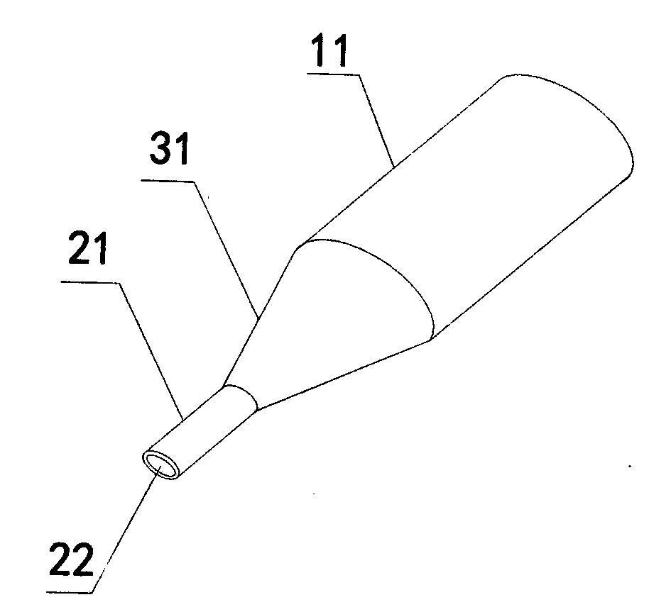
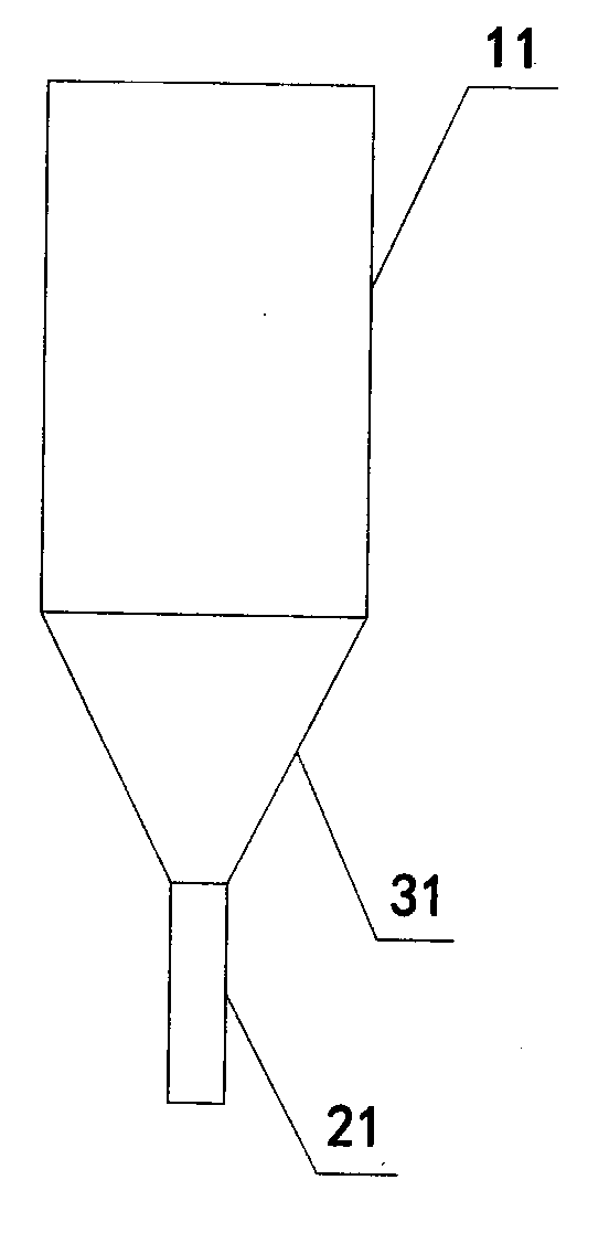
[0034] figure 1 , 2 Schematically provides a simplified structural diagram of the on-site ion source device under atmospheric pressure in the embodiment of the present invention, as figure 1 , 2 As shown, the ion source device includes:
[0035] The first cavity 11, the first cavity has an inlet, and the inside is hollow, such as cylindrical;
[0036] A discharge device, the discharge device is arranged in the first cavity; the discharge device can use a high-voltage electrode, a high-energy ultraviolet lamp or other discharge devices, which are all existing technologies in the field;
[0037] The second cavity 21 is hollow inside and communicates with the first cavity; the ratio R of the inner diameters of the first cavity and the second cavity 1 / R 2 Greater than or equal to 1.5, and less than or equal to 20; the outlet of the second cavity is used as the ion outlet 22; the inner diameter is the diameter of the smallest circle covering the section perpendicular to the a...
Embodiment 2
[0047] An application example of the on-site ion source device under atmospheric pressure and its working method in a mass spectrometry system according to Embodiment 1.
[0048] In this application example, both the first cavity and the second cavity adopt a cylindrical structure, and the third cavity is a hollow frustum structure for connecting the first cavity and the second cavity. The high-voltage electrode is arranged in the first cavity, the diameter of the first cavity is 10 mm, and the length is 20 mm; the diameter of the second cavity is 0.5 mm, and the length is 20 mm. The first cavity, the second cavity, and the third cavity are connected internally, and the internal gas pressure is adjustable, but the product of the pressure P and the length of the first cavity is greater than or equal to 1m·Pa and less than or equal to 20m·Pa .
[0049] The working process of the above-mentioned ion source device includes the following steps:
[0050] Under the action of the hi...
Embodiment 3
[0055] An application example of the on-site ion source device under atmospheric pressure and its working method in a mass spectrometry system according to Embodiment 1.
[0056] In this application example, both the first cavity and the second cavity adopt a cylindrical structure, and the third cavity is a hollow frustum structure for connecting the first cavity and the second cavity. The high-voltage electrode is arranged in the first cavity, the diameter of the first cavity is 4.5 mm, and the length is 10 mm; the diameter of the second cavity is 3 mm, and the length is 5 mm. The first cavity, the second cavity, and the third cavity are connected internally, and the internal gas pressure is adjustable, but the product of the pressure P and the length of the first cavity is greater than or equal to 1m·Pa and less than or equal to 20m·Pa .
[0057] The working process of the above-mentioned ion source device includes the following steps:
[0058] Under the action of the high...
PUM
 Abstract
Description
Claims
Application Information
 - R&D
- Intellectual Property
- Life Sciences
- Materials
- Tech Scout
- Unparalleled Data Quality
- Higher Quality Content
- 60% Fewer Hallucinations
Browse by: Latest US Patents, China's latest patents, Technical Efficacy Thesaurus, Application Domain, Technology Topic, Popular Technical Reports.
© 2025 PatSnap. All rights reserved.Legal|Privacy policy|Modern Slavery Act Transparency Statement|Sitemap|About US| Contact US: help@patsnap.com