
Erecting composite beam on-site section splicing girder construction technology of double guide beam bridge erecting machine

A construction process and technology of bridge erection machines, which are applied in the erection/assembly of bridges, bridge construction, bridges, etc., can solve the problems of high safety risk, high cost, and large amount of foundation construction work, and achieve high installation accuracy, construction safety, The construction effect is obvious

Active Publication Date: 2016-05-04
中交中南工程局有限公司
View PDF5 Cites 5 Cited by
  • Summary
  • Abstract
  • Description
  • Claims
  • Application Information

AI Technical Summary

Problems solved by technology

The installation of conventional auxiliary cross-span steel beams is implemented by large floating cranes or cross-pier gantry, construction assistance, foundation construction workload is large, and safety risks are high, and the cost is high

Method used


Image

  • Erecting composite beam on-site section splicing girder construction technology of double guide beam bridge erecting machine
  • Erecting composite beam on-site section splicing girder construction technology of double guide beam bridge erecting machine
  • Erecting composite beam on-site section splicing girder construction technology of double guide beam bridge erecting machine

Examples


Embodiment Construction

[0026] 1. Support design and construction

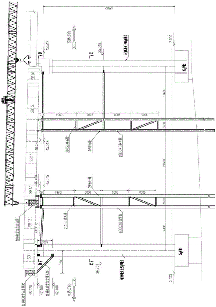
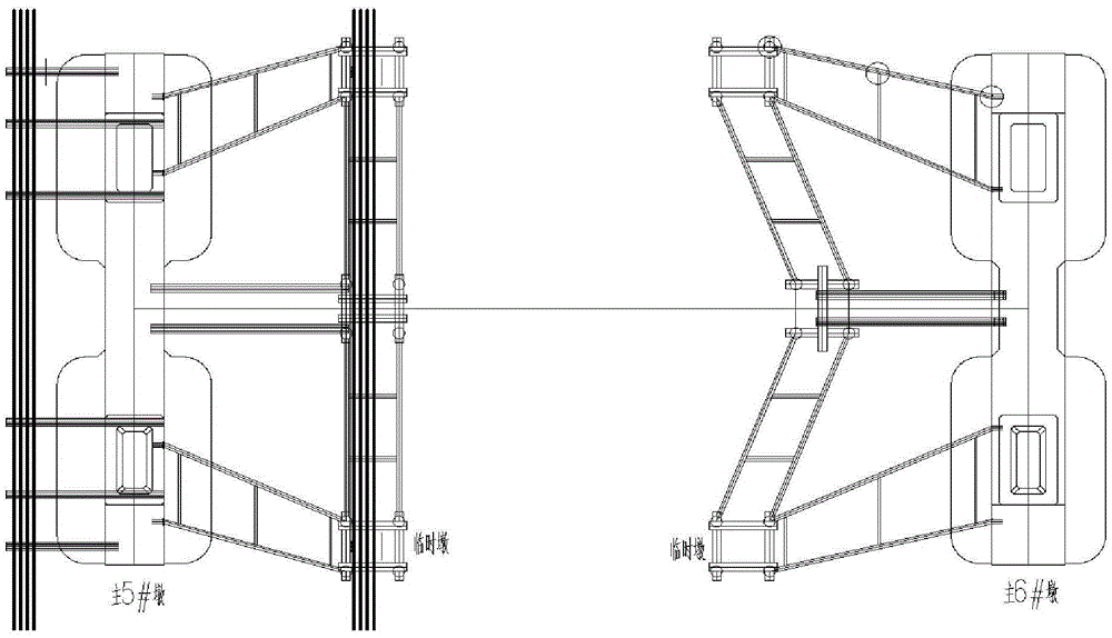
[0027] 1.1 as figure 1 with 2 As shown in the figure, steel pipe piles are used to form a temporary pier for the assembled support, and a supporting system is formed with the auxiliary pier and transition pier.

[0028] Auxiliary piers in the direction of the main bridge ( figure 1 Main 6# pier), transition pier in approach bridge direction ( figure 1 There are at least two temporary piers between the main 5# piers). For the convenience of description, the temporary piers are respectively 1# temporary piers and 2# temporary piers, and the temporary piers will be removed after the bridge structure construction is completed. The sequence is transitional pier, 1# temporary pier, 2# temporary pier and auxiliary pier.

[0029] 1.2 as figure 2 As shown, after the steel pipe piles are driven into the soil, a section steel stacking platform is set on the top of each temporary pier for loading and preloading. The section steel is proce...


PUM


Abstract

The invention discloses an erecting composite beam on-site section splicing girder construction technology of a double guide beam bridge erecting machine, and relates to the field of engineering construction. At least two temporary piers are arranged between an auxiliary pier and a transition pier, and the transition pier, the first temporary pier, the second temporary pier and the auxiliary pier are sequentially arranged; according to the bridge erecting machine, a deck of a guide bright forwards move to conduct stride flushing, a steel beam installed between the transition pier and the first temporary pier is spliced, and then a steel beam between the first temporary pier and the second temporary pier is spliced; a bridge erecting machine rail is placed on the installed steel beam; after the bridge erecting machine rail is installed, the bridge erecting machine forwards moves to enable a front support point to be placed at the pier top of the auxiliary pier; and a temporary beam conveying channel is formed in the top of a beam section of a steel beam between the transition pier and the first temporary pier, a beam section of a steel beam between the second temporary pier and the auxiliary pier is installed, the bridge erecting machine backwards moves to retreat back, and the temporary piers are dismounted. The erecting composite beam on-site section splicing girder construction technology is safe and efficient, the cost is reduced, the steel beam installation accuracy is high, and the problems that a barge or a large floating crane is influenced by ebb and flow, the construction operation time is short, and the on-water operation face limitation is large are solved.

Description

technical field [0001] The invention relates to a construction technology in the field of engineering construction, in particular to a construction technology for erecting steel-concrete composite beams to assist in spanning existing steel girders by using a double-guided girder bridging machine. Background technique [0002] With the advancement of science and technology and the rapid development of economy in our country, steel-concrete composite girder bridges, as a long-span structure, are widely used in highway and municipal fields. The steel-concrete composite girder bridge has the advantages of good fatigue resistance, reliable bearing capacity, saving steel, reducing beam height and increasing beam rigidity. [0003] For large-span steel-concrete composite girder bridges (I-shaped steel girders combined with concrete bridge decks), the installation of steel girders in the side and auxiliary spans is still difficult to construct, has a great impact on costs, and invol...

Claims


Application Information

Patent Timeline
IPC IPC(8): E01D21/06
CPCE01D21/06
Inventor 黄日生柏兴伟张帆巩智利范彬彬管永存
Owner 中交中南工程局有限公司
Learn More