
Design method for vertical type foundation pit supporting structure

A foundation pit support and design method technology, which is applied in the direction of basic structure engineering, excavation, construction, etc., can solve the problems of support removal, difficult control of construction quality, and weak displacement control ability, so as to achieve favorable soil uplift resistance and overall Stability is beneficial, the effect of enhancing stability

Pending Publication Date: 2016-05-04
SHANGHAI GEOTECHN INVESTIGATIONS & DESIGN INST
View PDF7 Cites 4 Cited by
  • Summary
  • Abstract
  • Description
  • Claims
  • Application Information

AI Technical Summary

Problems solved by technology

[0003] The advantages of the cement-soil gravity retaining wall are: there is no support in the general pit, which is convenient for rapid excavation, and has the dual functions of retaining soil and water stop, but the disadvantages are: weak displacement control ability, difficult to control construction quality, and general economy
[0004] The advantages of bored piles + in-pit support are: it is applicable to a wide range of soil properties and soil layers, and has little impact on the surrounding environment, but the disadvantages are: the cost per meter for shallow foundation pits is high, and the internal support has a great impact on excavation. Inconvenient, the support must be removed later, affecting the construction period
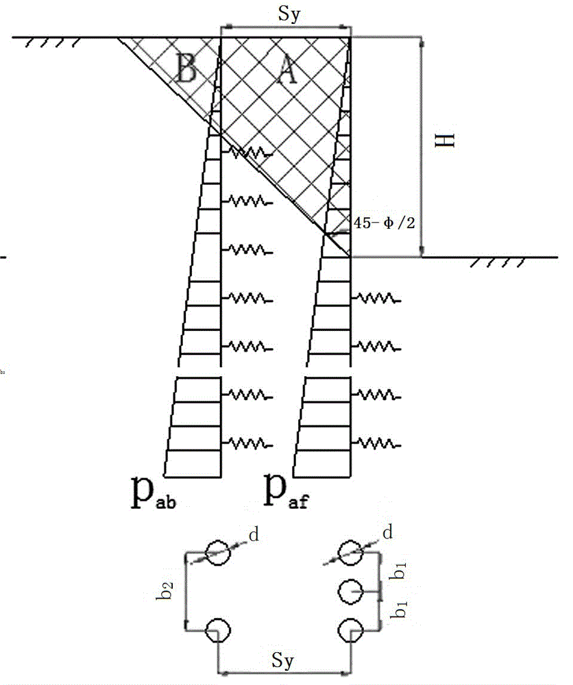
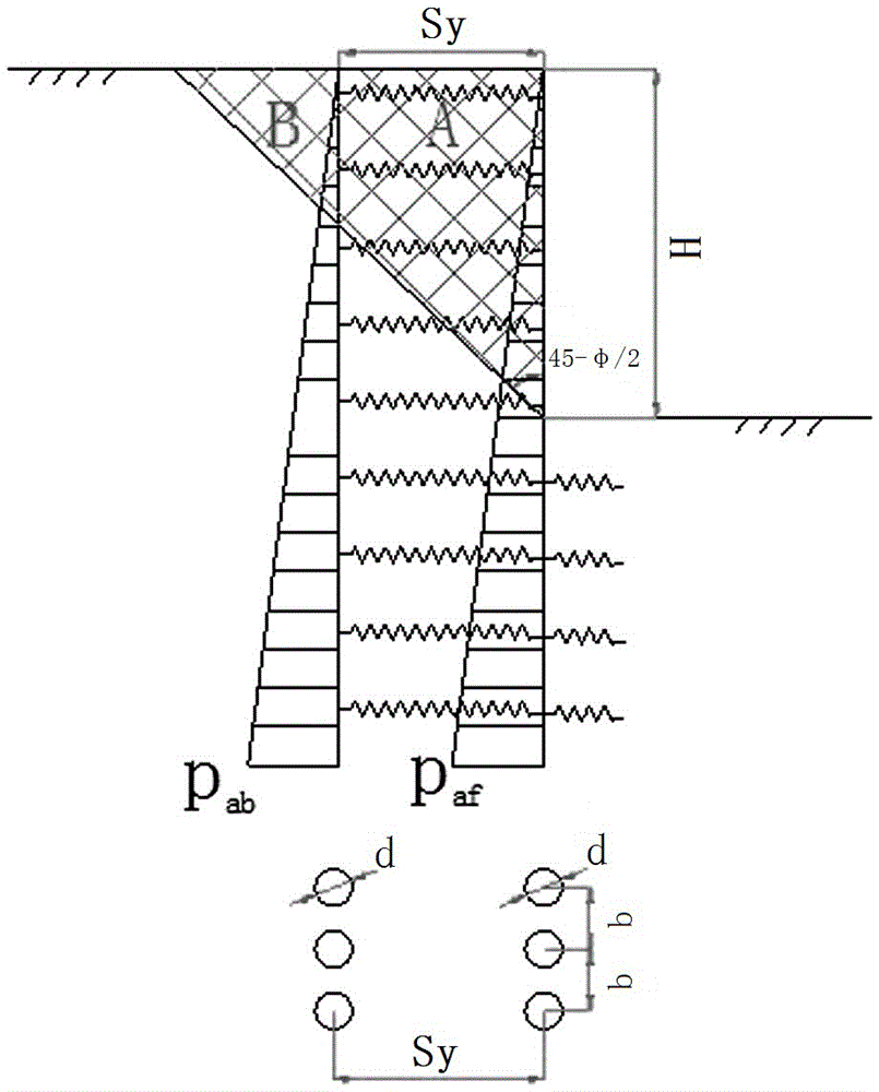
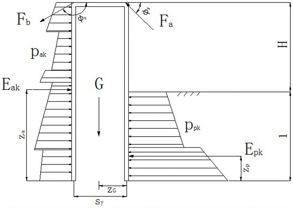
[0007] 1) In actual engineering, the distance between the front and rear rows of piles is usually dense at the front and sparse at the back. The diameter of the piles can be different, and the length of the piles can also be different. Neither the standard method nor the software based on the standard method can be used to calculate the actual project.
[0008] 2) The normative calculation model considers the shielding effect of the rear row of piles on the soil pressure of the front row of piles, but the distribution of the front and rear row of soil pressure has nothing to do with factors such as the distance between the rear row of piles, and its rationality remains to be discussed
[0009] 3) When the row spacing of the double-row piles is relatively large, the rationality of the soil between the piles as an elastic compression layer remains to be discussed

Method used


Image

  • Design method for vertical type foundation pit supporting structure
  • Design method for vertical type foundation pit supporting structure
  • Design method for vertical type foundation pit supporting structure

Examples


Embodiment 1

[0044] Embodiment one: if Figure 9 As shown, the inner support type vertical support structure in this embodiment includes support piles 2 and support body 4, wherein the support pile 2 adopts a single-row structure, which is arranged on the periphery of the foundation pit 6 and is vertical, and the support body 4 is used to support the support pile 2 so as to improve the support effect and stability of the support pile 2. A top pressure 1 is arranged on the top of the support pile 2 . The inner end of the top pressing 1 protrudes from the wall of the foundation pit 6 and faces into the foundation pit. One end of the support body 4 is connected and fixed with the pressure top 1 positioned at the pile top of the support pile 2, the support body 4 is inclined, and the other end is inserted into the bottom soil 7 of the foundation pit 6; at this time, due to the support The body 4 is inserted into the bottom soil body 7 to reinforce the bottom soil body 7 and resist the uplift...

Embodiment 2

[0077] Embodiment 2: Compared with Embodiment 1, this embodiment differs in that: Figure 11 , Figure 12 and Figure 13 As shown, what this embodiment adopts is the supporting body 4 of pull-out type.

[0078] Such as Figure 11 As shown, the pull-out vertical support structure includes a support pile 2 and a support body 4, wherein the support pile 2 adopts a single-row structure, which is arranged on the periphery of the foundation pit 6 and is vertical, and the support body 4 is used for pulling out The supporting pile 2 can improve the supporting effect and stability of the supporting pile 2 . A top pressure 1 is arranged on the top of the support pile 2 . The inner end of the top pressing 1 protrudes from the wall of the foundation pit 6 and faces into the foundation pit. One end of the supporting body 4 is connected and fixed with the topping 1 located at the pile top of the supporting pile 2, and the supporting body 4 is arranged obliquely, and it passes through t...

Embodiment 3

[0103] Embodiment three: the difference of this embodiment compared with embodiment one and two is: as Figure 16 and Figure 17 As shown, the support body 4 in this embodiment adopts a structural form of a combination of an inner support type and an outer pull type.

[0104] Such as Figure 16 As shown, the inner support and outer pull type vertical support structure includes support piles 2 and two support bodies 4 arranged obliquely, wherein the support piles 2 adopt a single-row structure, which are arranged on the periphery of the foundation pit 6 and are vertical, The support body 4 is used to support and pull the support pile 2 internally, so as to improve the support effect and stability of the support pile 2 . A top pressure 1 is arranged on the top of the support pile 2 . Among them, one end of a supporting body 4 that acts as an internal support for the supporting structure is connected and fixed to the topping 1 located outside the pile body of the supporting pi...


PUM


Abstract

The invention relates to the technical field of foundation pit engineering, in particular to a design method for a vertical type foundation pit supporting structure. The design method for the vertical type foundation pit supporting structure is characterized in that the supporting structure comprises a supporting pile and a supporting body. The design method specific to the double-row pile type supporting pile at least comprises the following steps that the supporting body is simplified into a supporting point of the foundation pit supporting structure according to the rigidity; the internal deformation force of the supporting pile and the supporting body under the soil pressure action is calculated; the resistance needed by the supporting body is calculated; and the included angle between the supporting body and the supporting pile and the length of the supporting body are calculated according to the resistance needed by the supporting body. The design method for the vertical type foundation pit supporting structure has the advantages that the vertical type foundation pit supporting structure has the multiple functions of reinforcement, soil blocking and water stopping, restrains deformation of a soil body, improves the stability of the wall of a foundation pit and realizes support-free or barrier-free construction in the pit; the related double-row pile soil pressure distribution theory research is disputed in the rock-soil field for a long time and no general agreement is achieved; monitoring data is the convincing measured data, the calculation mode is improved, and parameters are obtained through back calculation with the monitoring data, so that an effective way is provided to solve the problem.

Description

technical field [0001] The invention relates to the technical field of foundation pit engineering, in particular to a design method for a vertical foundation pit supporting structure. Background technique [0002] At present, the support structure for soft soil foundation pits generally adopts cement-soil gravity retaining walls or bored piles + pit support, but both have their own advantages and disadvantages. [0003] The advantages of the cement-soil gravity retaining wall are: there is no support in the general pit, which is convenient for rapid excavation, and has the dual functions of retaining soil and water stop, but the disadvantages are: weak displacement control ability, difficult to control construction quality, and general economy . [0004] The advantages of bored piles + in-pit support are: it is applicable to a wide range of soil properties and soil layers, and has little impact on the surrounding environment, but the disadvantages are: the cost per meter fo...

Claims


Application Information

Patent Timeline
IPC IPC(8): E02D17/04
CPCE02D17/04
Inventor 顾国荣杨石飞苏辉张静刘枫路家峰
Owner SHANGHAI GEOTECHN INVESTIGATIONS & DESIGN INST
Learn More