Modular automatic water stop device

An automatic blocking and modular technology, which is applied to door/window protection devices, flood control panels, windows/doors, etc., can solve the problems of troublesome transportation of automatic water blocking devices, difficult construction and installation, and increase construction costs, so as to save The effect of processing and construction period, saving transportation cost and saving maintenance cost

Active Publication Date: 2016-05-04
NANJING JUNLI TECH
View PDF13 Cites 77 Cited by
  • Summary
  • Abstract
  • Description
  • Claims
  • Application Information

AI Technical Summary

Problems solved by technology

[0002] In recent years, due to short-term torrential rains, urban waterlogging has also occurred from time to time, especially in underground garages. Because the water cannot be discharged in time, a large number of vehicles have been flooded. Similarly, huge property losses have also been caused.
The reason is that, on the one hand, the torrential rains in recent years have become more and more violent, and the inflow of water in the drainage design is insufficiently estimated; on the other hand, there are also technical difficulties, and it is difficult to take preventive measures, such as Use sandbags to block the water flow and prevent it from flowing into the garage from the garage exit, but the sandbags are difficult to carry
Chinese patent 201310576350.8 proposes an underground garage waterproof and submerged system, which needs to provide external power and monitor the water level to achieve water retention. The system is complex and the reliability is reduced; Floating barrel chambers and water storage tanks corresponding to multiple floating bucket chambers. The upper part of each water storage tank is connected to the corresponding floating bucket chamber through a water guide pipe, and a water grate is covered on the top of each water storage tank. A flood control baffle is provided on the top of each floating bucket chamber by rotating the shaft cover, and the reinforced support cover set in the floating bucket chamber is supported and arranged at the lower part of the flood control baffle, and each floating bucket chamber is provided with a floating bucket, the floating bucket The top is rotatably connected with one end of the reinforcement rod through a bearing, and the other end of the reinforcement rod is connected with the flood baffle through the reinforcement cover plate, and a drain pipe is connected to the lower side wall of each buoy chamber
When the structure is sunny or the amount of rain is small, the water retaining board is placed horizontally on the same level as the ordinary road. As the rainfall increases, it will automatically play the role of retaining water, but it is necessary to set up a floating bucket room, a storage tank, etc., and the system Complex, difficult to construct and install
[0003] Aiming at the problems to be solved in the above-mentioned prior art, the invention patent with the authorized announcement number CN204001916U has proposed a specific solution. The device does not need external force to drive, automatically retains water, and has a simple structure, low cost, and is easy to install. However, for specific When using a case building, first of all, it is necessary to separately book the size in advance, and then proceed to processing and installation. The entire processing and installation period is long, which affects the construction progress
Secondly, for installation and construction sites with large lengths, the transportation of the entire automatic water retaining device is very troublesome, requiring huge manpower and material resources, which increases the construction cost
Third, if the above invention patent is installed on a slope, there will be accumulated water in the base that cannot be discharged. Since the base is made of metal, the accumulated water will corrode the metal and shorten the life of the water retaining device.

Method used


Image

  • Modular automatic water stop device
  • Modular automatic water stop device
  • Modular automatic water stop device

Examples


Embodiment 1

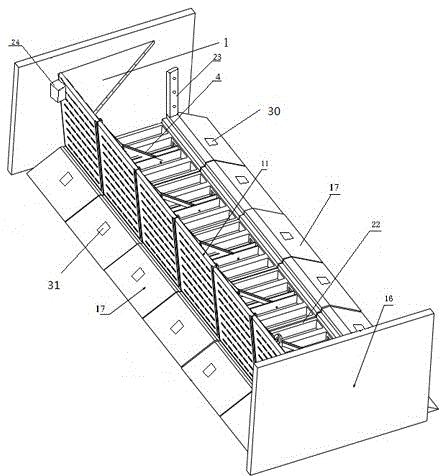
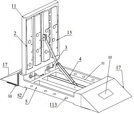
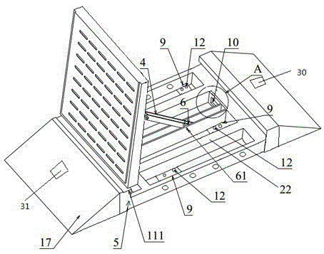
[0062] Such as figure 1 The modular automatic water retaining device shown is used to be fixed on the slope of the garage entrance and exit. The modular automatic water retaining device includes several automatic water retaining units arranged side by side. The automatic water retaining unit includes a base 5 And the panel 11, the base 5 is provided with more than two water storage chambers that run through the base up and down. The preferred number of water storage chambers in this embodiment is four, but it is not limited to only four. The water storage chambers are separated by beams 22 Separated, one end of the panel 11 is rotated on the base 5 through the hinge 3, and the panel 11 rotates to open and close the water storage chamber. The surface of the panel 11 that is used to cover the base 5 is provided with several floating plates 2, such as figure 2 , image 3 and Figure 4 As shown, the base 5 is different from the end of the rotational connection between the base ...

Embodiment 2

[0082] The difference between this embodiment and Embodiment 1 is that the buffer slope 17 and the base 5 are an integrated mechanism, there is no second water inlet and second water outlet, but only the first water inlet and the first water outlet, and the first water inlet runs through the The gentle slope on the side where it is located, and the first water outlet runs through the buffer slope on the side where it is located.

Embodiment 3

[0084] Such as Figure 19 As shown, the difference between this embodiment and Embodiment 1 is that this embodiment does not include buffer slopes 17 arranged on both sides of the base 5, and the rest of the structure is the same as Embodiment 1. When the height of the automatic water retaining device of the present invention is not When the automobile chassis and tires are damaged, the buffer slope 17 may not be provided. Generally when the height of the automatic water retaining device in the present application is less than four to five centimeters, the buffer slope 17 does not need to be provided.


PUM


Abstract

The invention discloses a modular automatic water stop device. The modular automatic water stop device comprises two or more automatic water stop units which are arranged in parallel in a line. Each automatic water stop unit comprises a panel and a base detachably installed on the ground, wherein a water storage cavity penetrating through the base vertically is formed in the base, one end of the panel is arranged on the base in a rotating mode, the water storage cavity is opened or closed when the panel rotates, a floating plate is arranged on the face, used for covering the base, of the panel, and a water inlet communicated with the water storage cavity is formed in the end, not connected with the panel, of the base. Every two adjacent bases are detachably connected. The modular automatic water stop device has the advantages that the automatic water stop device is simple in structure, convenient to machine and suitable for most water stop sites, the transport difficulty of the automatic water stop device is lowered, the use range of the automatic water stop device is widened, the installation construction cost and the machining cost of the automatic water stop device are reduced, the installation cycle is shortened, and the purpose of water stop for fixed buildings is rapidly and efficiently achieved.

Description

technical field [0001] The present invention relates to buildings or similar structures for the purpose of securing buildings, swimming or spray baths or pools, masts, fences, tents or canopies in general, structures for housing motor vehicles, railway vehicles, aircraft, boats or similar vehicles, For example, garages, garage special equipment or appliances not included in other categories, such as stabilizing devices, safety devices Technical field, especially related to the automatic water retaining device in the above-mentioned fields. Background technique [0002] In recent years, urban waterlogging due to short-term torrential rains has also occurred from time to time, especially in underground garages. Due to the inability to discharge water in time, a large number of vehicles have been flooded, and similarly, huge property losses have also been caused. The reason is that, on the one hand, the torrential rains in recent years have become more and more violent, and the...

Claims


Application Information

Patent Timeline
Patent Type & Authority Applications(China)
IPC IPC(8): E06B9/00
CPCE06B9/00E06B2009/007
Inventor 徐才奎其他发明人请求不公开姓名
Owner NANJING JUNLI TECH
Why Eureka
Try Eureka