Floating type automatic sucker rod screwing on and off device

A sucker rod, floating technology, applied in drill pipe, drilling equipment, earthwork drilling, etc., to achieve the effect of reducing quantity, high degree of integration, and reducing personal injury

Active Publication Date: 2016-05-04
SHANDONG SHENGLI PETROLEUM EQUIP IND TECH RES INST
View PDF4 Cites 17 Cited by
  • Summary
  • Abstract
  • Description
  • Claims
  • Application Information

AI Technical Summary

Problems solved by technology

Reverse action when buckle up

Method used


Image

  • Floating type automatic sucker rod screwing on and off device
  • Floating type automatic sucker rod screwing on and off device
  • Floating type automatic sucker rod screwing on and off device

Examples


Embodiment 1

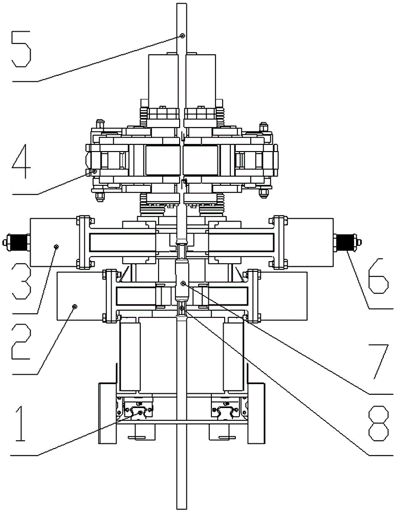
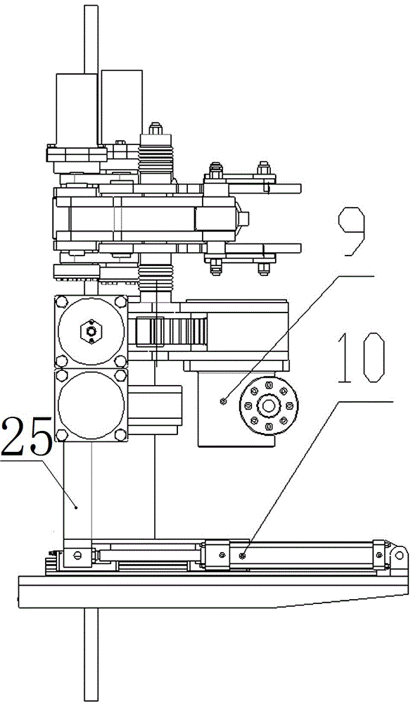
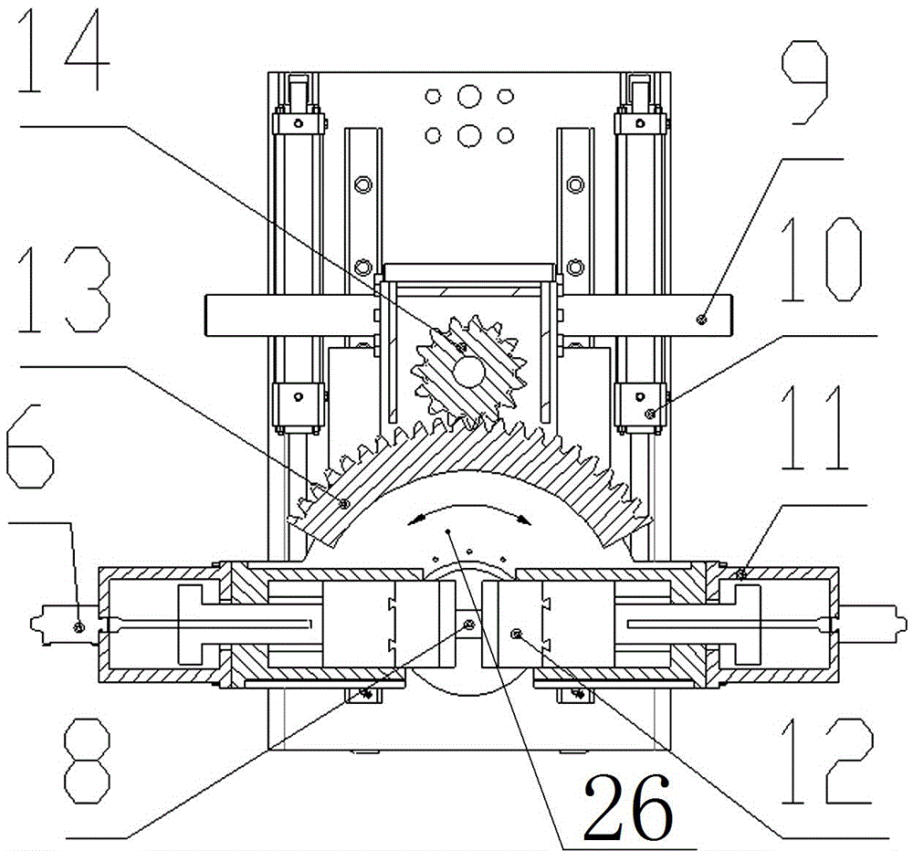
[0029] see Figure 1-6 , a floating sucker rod automatic on-off device, comprising a bracket 25, a guide rail 1, a back-up tong 2, a moving tong 3 and a rotating tong 4, wherein the back-up tong 2 and the moving tong are coaxially installed on the bracket 25 sequentially from bottom to top 3 and the rotary tong 4, the bracket 25 is installed on the guide rail 1 and moves laterally through the guide rail oil cylinder 10 installed on the guide rail 1; Reverse torque; the movable tongs 3 are used to clamp the wrench side of the second sucker rod and realize buckling and buckling. It includes a base and a clamping unit and a rotating unit installed thereon. The clamping unit includes a rotating seat 26 and The movable tong cylinder 11 installed on it and the tooth plate 12 driven by the movable tong cylinder 11 to move relatively laterally, the movable tong cylinder 11 is equipped with a displacement sensor; the swing unit includes a swing cylinder 9, a pinion 14 and a half ring g...

Embodiment 2

[0032] see Figure 1-6, a floating sucker rod automatic on-off breakout device, on the basis of Embodiment 1, the rotary tongs clamping cylinder 18 controls the rollers of each rotary tong to move closer to or away from each other through the linkage mechanism 17; the linkage mechanism 17 includes a fixed seat 19. Two movable seats 20 and connecting rod groups, the two movable seats 20 are respectively symmetrically installed on both sides of the fixed seat 19 through the connecting rod groups; wherein each connecting rod group includes a first connecting rod 21 and a second connecting rod 22. The first connecting rod 21 and the second connecting rod 22 are two arranged side by side; the middle part of the first connecting rod 21 is hinged to one side of the fixed seat 19, and the first end of the first connecting rod 21 is connected to the rotary clamp The clamping oil cylinder 18 is hinged, the second end is hinged with the outside of the movable seat 20, the first end of th...

Embodiment 3

[0035] see Figure 1-6 , a floating sucker rod automatic on-off device, on the basis of Embodiment 2, the first ends of the first connecting rods 21 connected to the two movable seats 20 are respectively hinged with third connecting rods 23 The other ends of the two third connecting rods 23 are connected at a certain angle relative to each other through a pin shaft; the fixed base 19 is fixed with a V-shaped fork body 24, and the pin shaft is located in the V-shaped fork body 24 and can move along it and be limited.

[0036] The working process is basically the same as that of Embodiments 1 and 2, and only the working process of the above-mentioned added structure will be described below. When the clamping cylinders 18 of the rotary tongs extend to both sides, the two third connecting rods 23 also move outwards respectively. Move, the angle between the two third connecting rods connecting rods 23 gradually increases until the two become a straight line, at this time it can con...


PUM


Abstract

A floating type automatic sucker rod screwing on and off device comprises a support, a back-up wrench, a moving wrench and a rotary wrench. The support is sequentially and coaxially provided with the back-up wrench, the moving wrench and the rotary wrench from bottom to top. The back-up wrench is used for clamping a coupling of a first sucker rod and providing reactive torque needed in screwing on and off. The moving wrench is used for clamping the wrench part of a second sucker rod and achieving tightening buckling and tight buckling. The rotary wrench is used for screwing off and screwing on the sucker rods. The floating type automatic sucker rod screwing on and off device has the advantages that the blank of the floating type automatic sucker rod screwing on and off device is filled in, full-automatic and intelligent development of a drilling rig is facilitated, the number of drilling operating personnel is reduced, the operating personnel are far away from a well mouth, the injuries of occurring accidents to the operating personnel are reduced, the integration degree is high, and modular design of downstream equipment is facilitated.

Description

technical field [0001] The invention relates to the field of oilfield workover equipment, in particular to a floating sucker rod automatic make-up and breakout device used for oilfield workover operations. Background technique [0002] The workover operation needs to raise and lower the downhole pipe string, and making-up and breaking-out of the pipe string is the most frequent process during the lifting and lowering process. At present, manual operation is generally used for making-up and breaking-out of the pipe string, especially the special structure of the sucker rod coupling, which must be completed manually during the make-up and break-out process, which restricts the degree of automation of workover equipment. At present, worldwide There is no automatic make-up and break-out device about the sucker rod, and the existing equipment has the following deficiencies: [0003] ①The existing make-up and break-out devices for sucker rods, butt joints, make-up and break-out, ...

Claims


Application Information

Patent Timeline
Patent Type & Authority Applications(China)
IPC IPC(8): E21B19/16
CPCE21B19/164
Inventor 王运安古仁龙刘睿刘东李涛张金鹏周扬理于海华郭枝鑫徐仁峰
Owner SHANDONG SHENGLI PETROLEUM EQUIP IND TECH RES INST
Why Eureka
Try Eureka