Integrated control system and device for drilling operation procedures

A process integration and drilling operation technology, which is applied to the automatic control system of drilling, drilling equipment, earthwork drilling and production, etc., can solve the problem that the automation degree and operation efficiency of the system cannot be further improved, the system operation process is not strong, and it cannot be well Ensure operational safety and operational efficiency, etc., to achieve the effect of improving the level of automatic operation, reducing misoperation, and improving the level of automatic cooperation

Active Publication Date: 2016-05-04
CHINA PETROCHEMICAL CORP +2
View PDF8 Cites 8 Cited by
  • Summary
  • Abstract
  • Description
  • Claims
  • Application Information

AI Technical Summary

Problems solved by technology

However, the integrated operation of the entire automated drilling rig does not carry out mode classification and operation according to the process mode of drilling operation, resulting in a weak system operation process, which cannot further improve the overall automation and operating efficiency of the system
Since the system is generally divided into the cooperative operation of the master and assistant drillers, the coordination and information exchange between the master and assistant drillers is required. Without the control of the drilling mode, many operations and cooperation between the master and assistant drillers depend on the operator. Identification, judgment and communication cannot well guarantee the safety and efficiency of operations

Method used


Image

  • Integrated control system and device for drilling operation procedures
  • Integrated control system and device for drilling operation procedures
  • Integrated control system and device for drilling operation procedures

Examples


Embodiment 1

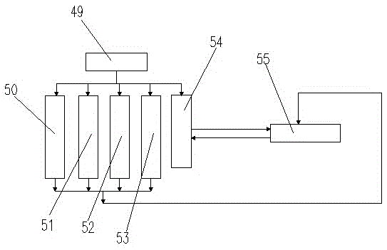
[0021] Pull-out mode 50 under master driller control mode 49

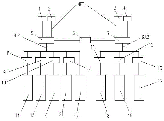
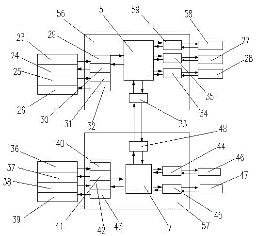
[0022] See attached Figure 1-3, set the system on No. 1 industrial machine 1 or No. 2 industrial machine 2 to the tripping mode 50, and the tripping mode 50 set by No. 1 industrial machine 1 or No. 2 industrial machine 2 is transmitted to the master driller CPU5 through the NET network , the master driller CPU5 transmits the tripping pattern 50 to the assistant driller CPU7 by connecting the network coupler 6, and the assistant driller CPU7 transmits the tripping pattern 50 signal to No. 3 industrial machine 3 or No. 4 industrial machine 4 through the NET network, After the transmission is completed, the tripping mode 50 automatically enters the main driller's operation panel 25 and the assistant driller's operation panel 38 through the main driller's digital input (DI) module 31 and the assistant driller's digital input (DI) module 42 respectively. In the drilling mode 50, the main driller CPU5 transmits the sig...

Embodiment 2

[0024] Drill down mode 51 under master driller control mode 49

[0025] see Figure 1-3 , set the drill-down mode 51 on No. 1 industrial machine 1 or No. 2 industrial machine 2, and the drill-down mode 51 set by No. 1 industrial machine 1 and No. 2 industrial machine 2 is transmitted to the master driller CPU5 through the NET network, Then it is transmitted to the assistant driller CPU7 by connecting the network coupler 6, and the assistant driller CPU7 transmits the signal to No. 3 industrial machine 3 or No. 4 industrial machine 4 through the NET network. The Driller Digital Input (DI) module 31 and the Assistant Driller Digital Input (DI) module 42 enter the Master Driller Operations Panel 25 and the Assistant Driller Operations Panel 38 . In the down-drilling mode 51, the main driller CPU5 transmits the high gear signal to the remote station 17 of the valve island through the BUS1 network. Driller CPU5, and the signal is input to the electronic brake device 58 through th...

Embodiment 3

[0027] Build Root Mode 53 in Master Driller Control Mode 49

[0028] see Figure 1-3, set and establish the root mode 53 on No. 1 industrial machine 1 or No. 2 industrial machine 2, transmit it to the main driller CPU5 through the NET network, and then transmit it to the assistant driller CPU7 by connecting the network coupler 6, and the assistant driller CPU7 passes NET network transmits the signal to No. 3 industrial machine 3 or No. 4 industrial machine 4. After the transmission is completed, the root mode 53 is established and automatically passed through the main driller digital input (DI) module 31 and the assistant driller digital input (DI) module 42 respectively. Access the master driller's operating panel 25 and the assistant driller's operating panel 38 . Under the establishment of root mode 53, the main driller CPU5 transmits the high gear signal to the valve island remote station 17 through the BUS1 network. Drill CPU5, chief driller's analog output (AO) module ...


PUM


Abstract

The invention provides an integrated control system and device for drilling operation procedures. A first industrial machine, a second industrial machine, a third industrial machine and a fourth industrial machine are connected with a main driller CPU and an assistant driller CPU through a NET network respectively, the main driller CPU and the assistant driller CPU are connected with each other through a linked network coupler, the main driller CPU is connected with a first main driller network coupler, a second main driller network coupler, a third main driller network coupler, a fourth main driller network coupler, a valve terminal remote station, a host controller, a top drive controller, an instrument controller and an automatic driller feeding controller through a BUS1, and the assistant driller CPU is connected with a catwalk controller, a tube tank controller and an iron roughneck controller through a BUS2, a first assistant driller network coupler, a second assistant driller network coupler and a third assistant driller network coupler. According to the system and device, the mode that main driller mode selecting is taken as the principal thing, and an assistant driller is operated in a slaved mode is adopted by the system, and therefore linkage and interlocking between a main driller and the assistant driller are improved; the sequential operation steps are regulated by the device, therefore, misoperation is reduced, and the equipment safety is improved.

Description

technical field [0001] The invention relates to the field of automatic integrated control of oil drilling equipment, in particular to a system and device for integrated control of drilling operation process. Background technique [0002] With the operating requirements of reducing staff and increasing efficiency in major oilfields, the current oilfield drilling equipment is gradually developing towards automatic drilling rigs equipped with automatic operation tools. Most of the existing conventional driller integrated control systems include the following systems: highly integrated driller integrated multifunctional operating chair, intelligent anti-collision system to prevent interference and collision between subsystems, data recording and information management system. However, the integrated operation of the entire automated drilling rig is not operated according to the mode classification of the drilling operation process mode, resulting in a weak system operation proce...

Claims


Application Information

Patent Timeline
Patent Type & Authority Applications(China)
IPC IPC(8): E21B44/00
CPCE21B44/00
Inventor 马伟刘洪亮陈健许贞文李勇
Owner CHINA PETROCHEMICAL CORP
Why Eureka
Try Eureka