

Open water pump and water tank groove cleaning machine with same
A sink type cleaning machine, open technology, applied in the direction of cleaning methods using liquids, non-variable volume pumps, parts of pumping devices for elastic fluids, etc., can solve the high requirements of shape and structure, impeller and The processing technology of the water tank body is complex, and there are many cleaning machine parts, which can achieve the effect of simplifying the parts and processing technology, reducing the number of parts, and simplifying the structure.
- Summary
- Abstract
- Description
- Claims
- Application Information
AI Technical Summary
Problems solved by technology
Method used
Image

Examples
Embodiment Construction
[0025] The present invention will be further described in detail below in conjunction with the accompanying drawings and embodiments.
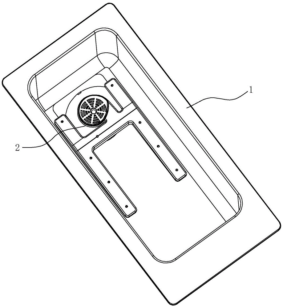
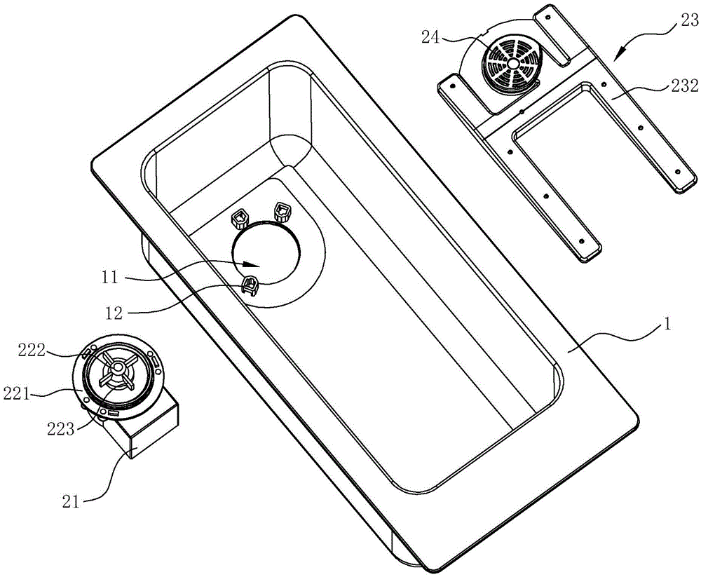
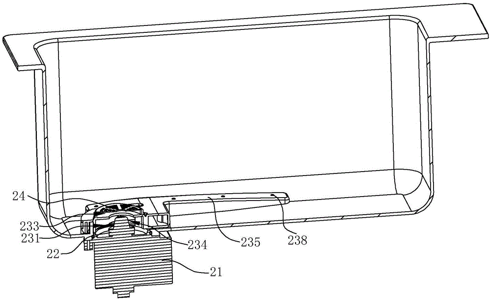
[0026] see Figure 1 ~ Figure 3 , a sink type cleaning machine, including a sink body 1 and an open water pump 2, the open water pump 2 includes a motor 21, an impeller 22 and a casing 23, wherein the motor 21 is located under the bottom of the sink body 1, and the impeller 22 and the casing The body 23 is located in the bottom of the sink body 1 .
[0027] The bottom of the tank body 1 is provided with an opening 11 , the motor 21 is located below the opening 11 of the tank body 1 and corresponds to the position of the opening 11 , and its output shaft extends upwards into the tank body 1 through the opening 11 . The impeller 22 includes a chassis 221 adapted to the shape and size of the opening 11 , a central shaft 222 and a plurality of blades 223 . The chassis 221 is installed at the opening 11 to close the opening 11 , thereby preventin...
PUM
 Abstract
Description
Claims
Application Information