Modular LED panel light

A technology of LED panel lights and backlight modules, which is applied to lighting devices, cooling/heating devices of lighting devices, light sources, etc., can solve the problems of unstable overall structure of panel lights, single shape and structure, poor heat dissipation effect, etc., to achieve Effects of richness, soft light, and improved heat dissipation performance

Inactive Publication Date: 2016-05-04
BENCHAMARK LIGHTING SUZHOU CO LTD
View PDF7 Cites 0 Cited by
  • Summary
  • Abstract
  • Description
  • Claims
  • Application Information

AI Technical Summary

Problems solved by technology

[0009] The purpose of the present invention is to overcome the disadvantages of the existing LED panel lamps, such as poor heat dissipation effect, single shape structure, poor decorative effect, unstable overall structure of the panel lamp, and easy to be damaged during packaging and transportation, and provides a module LED panel light

Method used


Image

  • Modular LED panel light
  • Modular LED panel light
  • Modular LED panel light

Examples


Embodiment 1

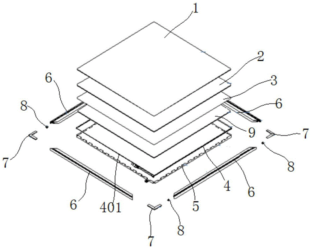
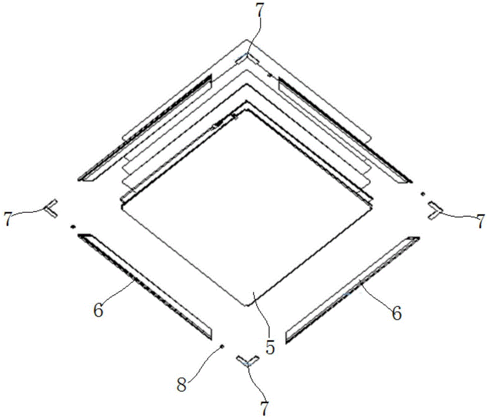
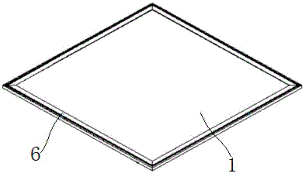
[0042] With reference to the accompanying drawings, a modular LED panel light of this embodiment includes a backlight module, a frame 6 and a heat dissipation back cover 5 located at the bottom of the backlight module, wherein the backlight module is wrapped in the heat dissipation back cover 5 and the edge of the heat dissipation rear cover 5 is accommodated in the installation groove 603 inside the frame 6 . Such as Figure 5 , Image 6 As shown, the above-mentioned heat dissipation rear cover 5 includes a heat dissipation bottom plate 503, a heat dissipation frame 502, and heat dissipation teeth 501 uniformly distributed along the circumference of the top of the heat dissipation rear cover 5. The heat dissipation teeth 501, the heat dissipation frame 502 and the heat dissipation bottom plate 503 together form a housing space for the backlight module. Such as figure 1 , figure 2 As shown, the backlight module of this embodiment includes a PCB light bar 4, a diffuser pla...

Embodiment 2

[0050] The difference between this embodiment and Embodiment 1 is that the ratio of the distance between the heat dissipation fins 501 on the same side of the heat dissipation rear cover 5 to the length of the heat dissipation fins 501 is 0.8.

Embodiment 3

[0052] The difference between this embodiment and Embodiment 1 is that the ratio of the distance between the heat dissipation fins 501 on the same side of the heat dissipation rear cover 5 to the length of the heat dissipation fins 501 is 0.5.


PUM


Abstract

The invention discloses a modular LED panel light, and belongs to the technical field of lighting sources. The modular LED panel light comprises a backlight module, frames and a rear cooling cover located at the bottom of the backlight module, wherein the backlight module is wrapped with the rear cooling cover, and the edges of the rear cooling cover are accommodated in mounting grooves in the inner sides of the frames. The rear cooling cover comprises a bottom cooling plate, cooling frames and cooling teeth evenly distributed on the top of the rear cooling cover in the circumferential direction of the rear cooling cover, and a space for accommodating the backlight module is jointly formed by the cooling teeth, the cooling frames and the bottom cooling plate. According to the modular LED panel light, the mode of cooling through frames of an existing LED panel light is changed to the mode that cooling is conducted mainly through the rear cooling cover and assisted by the frames, so that the cooling area is obviously enlarged, and the cooling effect is obviously improved; impact resistance and extrusion resistance of the modular LED panel light are guaranteed through organic separation of an optical cooling module and a mechanical module of the LED panel light, and the optical cooling module is effectively protected.

Description

technical field [0001] The invention belongs to the technical field of lighting sources, and more specifically relates to a modularized LED panel light. Background technique [0002] Traditional lighting products generally use light sources such as incandescent lamps, fluorescent lamps, halogen lamps or high-pressure gas discharge lamps as light sources. Such lighting products have the following defects: 1. High power consumption, high heat generation, and no energy saving; 2. Lamp volume It is generally large, takes up space, and the light source is easily broken; 3. There is ultraviolet light pollution, and the stroboscopic light will cause serious harm to human eyes; 4. The toxic metal mercury will cause pollution and harm to the environment; 5. Service life Short and high maintenance cost. [0003] In order to solve the above-mentioned defects of traditional lighting products and develop in the direction of energy saving, environmental protection, safety and health, peo...

Claims


Application Information

Patent Timeline
Patent Type & Authority Applications(China)
IPC IPC(8): F21K9/20F21V13/12F21V17/00F21V19/00F21V29/74F21Y115/10
CPCF21V13/12F21V17/00F21V19/001
Inventor 张群波罗玉杰杨建徐伟
Owner BENCHAMARK LIGHTING SUZHOU CO LTD
Why Eureka
Try Eureka