Flame stabilizer

A flame stabilizer and wall technology, which is applied to combustion methods, combustion chambers, combustion equipment, etc., can solve the problem of air-fuel lean and other problems, improve the quality and energy exchange rate, widen the lean oil flameout boundary, and widen the stable combustion range. Effect

Active Publication Date: 2016-05-04
AECC SHENYANG ENGINE RES INST
View PDF6 Cites 10 Cited by
  • Summary
  • Abstract
  • Description
  • Claims
  • Application Information

AI Technical Summary

Problems solved by technology

[0004] The purpose of the present invention is to provide a flame stabilizer, which at least solves the problem that the mixed gas and oil gas in the recirculation zone of the existing flame stabilizer are relatively poor

Method used


Image

  • Flame stabilizer
  • Flame stabilizer
  • Flame stabilizer

Examples


Embodiment Construction

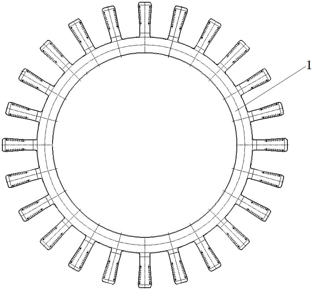
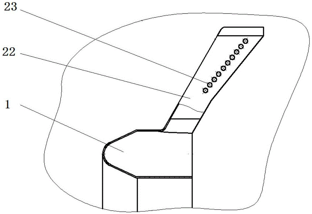
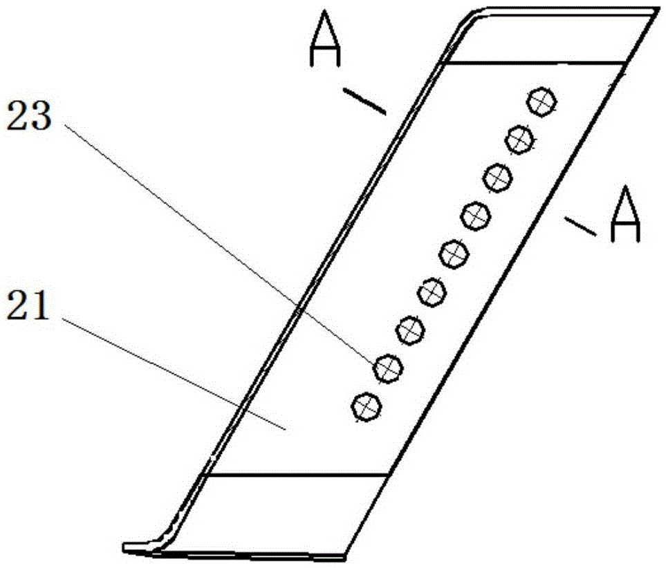
[0017] In order to make the objectives, technical solutions and advantages of the present invention clearer, the technical solutions in the embodiments of the present invention will be described in more detail below in conjunction with the drawings in the embodiments of the present invention. In the drawings, the same or similar reference numerals denote the same or similar elements or elements having the same or similar functions throughout. The described embodiments are some, but not all, embodiments of the invention. The embodiments described below by referring to the figures are exemplary and are intended to explain the present invention and should not be construed as limiting the present invention. Based on the embodiments of the present invention, all other embodiments obtained by persons of ordinary skill in the art without creative efforts fall within the protection scope of the present invention. Embodiments of the present invention will be described in detail below ...


PUM


Abstract

The invention relates to an aviation gas turbine engine afterburner flame stabilization technology, in particular to a flame stabilizer which at least solves the problem that mixed gasoline gas in a recirculation zone of the conventional flame stabilizer is lean. The flame stabilizer is positioned in an outer duct of an afterburner, and is a radial flame stabilizer which extends outwards from an annular flame stabilizer at a junction of an inner duct and the outer duct; the flame stabilizer is provided with a first wall surface and a second wall surface that are symmetrically distributed; and a plurality of air suction holes are symmetrically formed in the first wall surface and the second wall surface. Low-pressure air in the recirculation zone can be used to suck liquid-state fuel oil nearby the wall surfaces of the flame stabilizer, and a lean oil flameout boundary of the flame stabilizer can be widened. In addition, a mass-energy exchange rate in the recirculation zone can be increased, the combustion efficiency of the flame stabilizer can be improved, and the stable combustion range can be widened.

Description

technical field [0001] The invention relates to a flame stabilization technology for an afterburner of an aviation gas turbine engine, in particular to a flame stabilizer. Background technique [0002] The afterburner of a turbojet engine mainly uses a blunt body flame stabilizer to stabilize and spread the flame. At present, the flame stabilizer mainly adopts V-shaped groove stabilizer. In the turbofan engine afterburner, the temperature of the airflow flowing into the afterburner through the engine outer culvert is relatively low, generally not exceeding 250°C. [0003] In such a low-temperature airflow, due to poor evaporation conditions, a large amount of liquid fuel cannot be evaporated due to the poor evaporation conditions of the fuel injected from the afterburner fuel nozzle, resulting in poor gas mixture in the return area of ​​the flame stabilizer and a liquid oil film on the surface of the stabilizer. The state of flow and evaporation is not well controlled, whic...

Claims


Application Information

Patent Timeline
Patent Type & Authority Applications(China)
IPC IPC(8): F23R3/18
CPCF23R3/18
Inventor 李孝堂李江宁
Owner AECC SHENYANG ENGINE RES INST
Why Eureka
Try Eureka