Mechanical adherent flexible coupling probe for geological detection
A technology for geological exploration and coupling probes, applied in the direction of seismic signal receivers, etc., can solve the problems of cleaning butter, affecting the signal transmission effect, poor detection effect, etc., achieving the effect of easy recovery, ensuring the signal transmission effect, and convenient installation.
- Summary
- Abstract
- Description
- Claims
- Application Information
AI Technical Summary
Problems solved by technology
Method used
Image
Examples
Embodiment 1
[0059] like figure 1 As shown, a wall-mounted flexible coupling probe for mechanical geological exploration includes a sleeve 1, and an oscillatory wave sensor 2 installed in the sleeve 1, and an axial flexible mechanical limit head is installed at the front end of the sleeve 1 , a prime mover mechanism is installed in the cavity in the middle of the sleeve 1, and the prime mover mechanism is connected with a radial expansion mechanism; after the prime mover mechanism is driven by the prime force, the radial expansion mechanism is driven to expand outward from the side wall of the sleeve 1 .
[0060] The oscillatory wave sensor 2 is a seismic wave sensor.
[0061] The prime mover is a rotary drive mechanism.
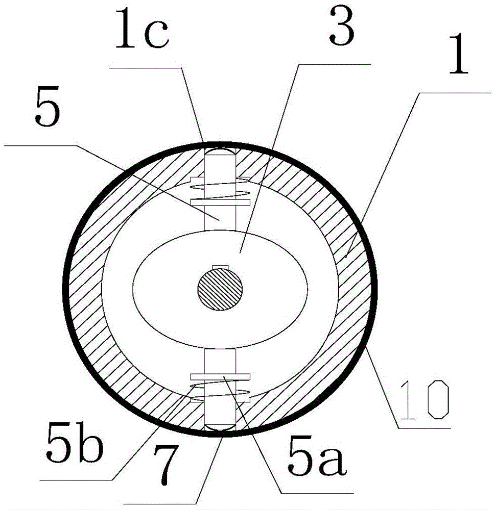
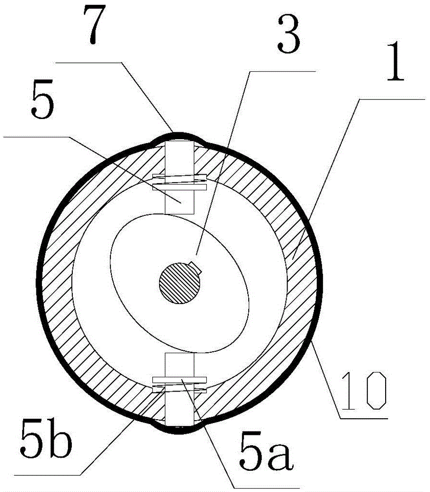
[0062] like figure 2 , 3 As shown, the prime mover mechanism includes an oval cam 3, which is driven to rotate by a motor 4, and a sliding tappet 5 abuts on the outer edge of the cam 3, and the sliding tappet 5 extends into the side of the sleeve 1 The via hole 1c ...
Embodiment 2
[0073] The second embodiment has the same principle as the first embodiment, but its prime mover mechanism is also a rotary drive mechanism. But its rotary drive mechanism is real impeller:
[0074] like Figure 4 As shown, the prime mover mechanism includes an impeller-shaped turntable 13, which is driven to rotate by a motor 4, and a sliding tappet 5 abuts on the outer edge of the turntable 13, and the sliding tappet 5 extends into the sleeve 1 The via hole 1c on the side wall is limited by the via hole 1c.
[0075] The sliding tappet 5 is provided with a boss 5 a , a return spring 5 b is sleeved on the sliding tappet 5 , and the return spring 5 b abuts between the boss 5 a and the inner wall of the sleeve 1 .
[0076] The rear end of the sliding tappet 5 is in contact with the turntable 13 , and the front end of the sliding tappet 5 is installed with a deformation spring 7 .
[0077] The impeller-shaped turntable 13 is provided with three blades, each blade is correspond...
Embodiment 3
[0080] The working principle of the third embodiment is different from that of the first embodiment, and the prime mover mechanism is a linear drive mechanism.
[0081] like figure 1 As shown, the linear drive mechanism includes a screw 6, which is driven to rotate by a motor 4, a sliding nut 9 is sleeved on the screw 6, and at least two lugs 9a are fixed on the sliding nut 9, and the lugs 9a are used as moving points. It is connected to one end of the deformation spring 7 , and the other end of the deformation spring 7 is connected to the sleeve 1 .
[0082] The sleeve 1 is provided with a linear chute, and the support lugs 9a slide in the linear chute.
[0083] The sliding nut 9 is connected with at least three deformation springs 7 , and all the deformation springs 7 are evenly distributed on the outer wall of the sleeve 1 .
[0084] The screw 6 is connected with the oscillatory wave sensor 2 .
PUM
 Abstract
Description
Claims
Application Information
 - R&D
- Intellectual Property
- Life Sciences
- Materials
- Tech Scout
- Unparalleled Data Quality
- Higher Quality Content
- 60% Fewer Hallucinations
Browse by: Latest US Patents, China's latest patents, Technical Efficacy Thesaurus, Application Domain, Technology Topic, Popular Technical Reports.
© 2025 PatSnap. All rights reserved.Legal|Privacy policy|Modern Slavery Act Transparency Statement|Sitemap|About US| Contact US: help@patsnap.com


