
Optical interconnection assembly

An optical interconnection and component technology, applied in the field of optical communication, can solve problems such as increasing product cost, achieve the effects of simple assembly, saving complex processes and reducing costs

Active Publication Date: 2016-05-04
WUHAN TELECOMM DEVICES
View PDF4 Cites 9 Cited by
  • Summary
  • Abstract
  • Description
  • Claims
  • Application Information

AI Technical Summary

Problems solved by technology

One of the traditional methods is to use 90° lens or prism for bending; the other is to use soft tape to realize 90° electric bending, so as to achieve the coupling effect indirectly, but both of these solutions will undoubtedly increase the product cost

Method used


Image

  • Optical interconnection assembly
  • Optical interconnection assembly
  • Optical interconnection assembly

Examples


Embodiment Construction

[0021] The present invention will be described in further detail below in conjunction with specific embodiments and accompanying drawings. Embodiments of the present invention are described in detail below, examples of which are shown in the drawings, wherein the same or similar reference numerals designate the same or similar elements or elements having the same or similar functions throughout. The embodiments described below with reference to the accompanying drawings are exemplary, and are only used to explain the technical solution of the present invention, and should not be construed as limiting the present invention.

[0022] In the description of the present invention, the orientation or positional relationship indicated by the terms "inner", "outer", "longitudinal", "transverse", "upper", "lower", "top", "bottom" etc. are based on the drawings The orientations or positional relationships shown are only for the convenience of describing the invention and do not require ...


PUM


Abstract

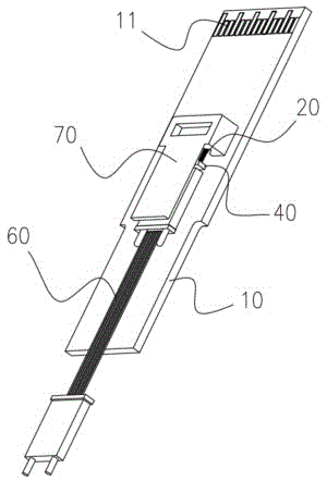
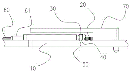
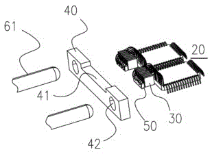
The present invention provides an optical interconnection assembly. The optical interconnection assembly comprises a PCB board, an IC chip with the PCB board as a carrier and a heat sink adhere to transition blocks and a VCSEL chip. The transition block includes a single-channel gold-plated layer and a multi-channel gold-plated layer, the single-channel gold-plated layer includes a whole top face gold-plated layer and a whole side face gold-plated layer connected with the whole top face gold-plated layer, and the multi-channel gold-plated layer includes multi-channel top face gold-plated layers which have top faces arranged at intervals and multi-channel side face gold-plated layers which are respectively connected with the multi-channel top face gold-plated layers with sides arranged at intervals; and the top of the heat sink is provided with a concave part, and when the transition blocks of the single-channel gold-plated layer or the multi-channel gold-plated layer is selected, two transitions on the range may be held, wherein the top face gold-plated layers on the transition blocks are connected with the IC chip through golden wires and the side face gold-plated layers on the transition blocks are connected with the VCSEL chip through the golden wires. According to the invention, the technical problem is solved that gold-plated layers are used for replacing a soft circuit or a lens conduction bending optical path, so that the manufacture is convenient, the cost is low and the yield of the products is improved.

Description

technical field [0001] The invention relates to the technical field of optical communication, in particular to an optical interconnection component. Background technique [0002] Optical interconnect modules are favored by the data market because of their light weight, low power consumption, and low cost. Today, data communication has achieved unprecedented development, and the market demand is rising steadily. At the same time of mass application, customers have new requirements for cost reduction. [0003] Since the chip selected by the module is a VCSEL (Vertical Light Emitting) chip, to make the light enter the flat optical fiber, it is necessary to realize the 90° bending of the light. One of the traditional methods is to use 90° lens or prism for bending; the other is to use soft tape to realize 90° electric bending, so as to indirectly achieve the coupling effect, but these two solutions will undoubtedly increase the product cost. Contents of the invention [000...

Claims


Application Information

Patent Timeline
Patent Type & Authority Applications(China)
IPC IPC(8): G02B6/42
CPCG02B6/4236G02B6/4268G02B6/4274
Inventor 何明阳曹芳周艳阳薛原杨昌霖张德玲王雨飞
Owner WUHAN TELECOMM DEVICES
Learn More