Micro-light-emitting diode

A light-emitting diode, miniature technology, applied in electrical components, electric solid-state devices, circuits, etc., can solve the problem of high brightness of light-emitting diode displays, and achieve the effect of increasing current density and increasing efficiency

Active Publication Date: 2016-05-04
MIKRO MESA TECH
View PDF4 Cites 8 Cited by
  • Summary
  • Abstract
  • Description
  • Claims
  • Application Information

AI Technical Summary

Problems solved by technology

Otherwise, the brightness of the LED display will be too large

Method used


Image

  • Micro-light-emitting diode
  • Micro-light-emitting diode
  • Micro-light-emitting diode

Examples


Embodiment Construction

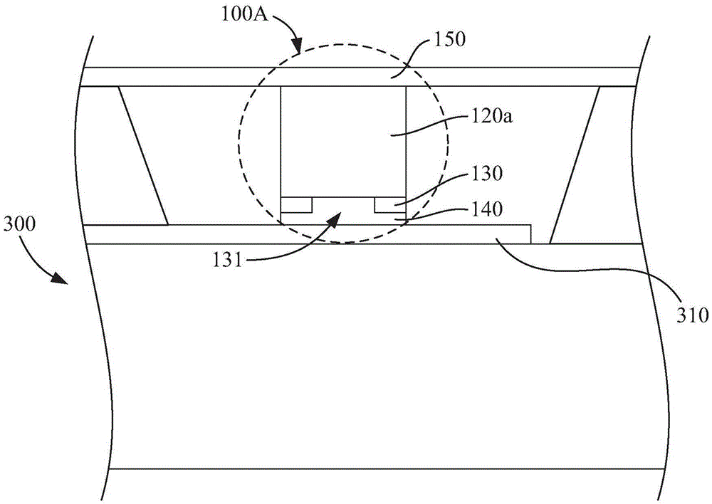
[0073] A number of embodiments of the present invention will be disclosed in the following figures. For the sake of clarity, many practical details will be described together in the following description. It should be understood, however, that these practical details should not be used to limit the invention. That is, in some embodiments of the present invention, these practical details are unnecessary. In addition, for the sake of simplifying the drawings, some conventional structures and elements will be shown in a simple and schematic manner in the drawings.

[0074] Embodiments of the invention describe miniature semiconductor components and methods of forming arrays of miniature semiconductor components, such as miniature light emitting diodes, for transfer to a receiving substrate. For example, the receiving substrate may be, but not limited to, a display substrate.

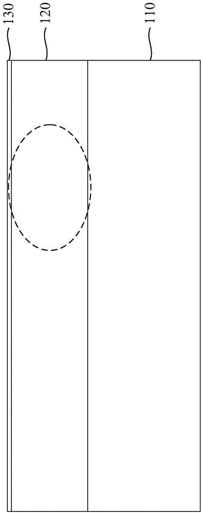
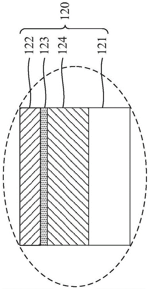
[0075] In different implementation manners, related descriptions may refer to accompanying drawings. ...


PUM


Abstract

The invention discloses a micro-light-emitting diode. The micro-light-emitting diode comprises a first-type semiconductor layer, a second-type semiconductor layer, a first current control layer, a first electrode and a second electrode. The second-type semiconductor layer is connected with the first-type semiconductor layer. The first current control layer is connected to the first-type semiconductor layer, and is provided with at least one opening in the first-type semiconductor layer. The first electrode is electrically coupled to the first-type semiconductor layer. The second electrode is electrically coupled to the second-type semiconductor layer. At least one of the first and second electrodes is provided with a light transmission part, vertical projection of the first current control layer on at least one of the first and second electrodes is partially overlapped with the light transmission portion, and the light transmission portion is transparent or semi-transparent. Thereby the micro-light-emitting diode is provided with a small light-emitting area, so the light-emitting area of the micro-light-emitting diode can be continue being shrinked, and the dimension of the micro-light-emitting diode is maintained.

Description

technical field [0001] The invention relates to a miniature light-emitting diode. Background technique [0002] In recent years, light-emitting diodes (light-emitting diodes, LEDs) have been commonly used in general and commercial lighting applications. As a light source, light-emitting diodes have many advantages, including lower energy consumption, longer life, smaller size, and faster switching speed. Therefore, traditional lighting sources, such as incandescent lamps, are gradually being replaced by light-emitting diode light sources. In an LED, when electrons and holes recombine across the semiconductor bandgap, the recombination energy is emitted in the form of photons and produces light. This recombination mechanism is the so-called radiative recombination. [0003] In LED displays using miniature LED arrays, in order to provide adequate brightness, eg, 500 nits (nit) to 1000 nits, the average emitted energy per LED must be reduced. Otherwise, the brightness of the...

Claims


Application Information

Patent Timeline
Patent Type & Authority Applications(China)
IPC IPC(8): H01L33/38H01L25/075
CPCH01L25/075H01L33/38H01L24/83H01L33/145H01L2224/73104H01L2224/83191H01L2924/0002
Inventor 陈立宜张珮瑜詹志辉张俊仪林师勤李欣薇
Owner MIKRO MESA TECH
Why Eureka
Try Eureka