TE mode dielectric resonator device

A dielectric resonator and dielectric resonance technology, which is applied in the field of communication, can solve the problems of large force on the bottom of the lower support, deterioration of near-end suppression, and influence on the electrical performance of TE mode dielectric resonators, so as to achieve uniform force and improve passive Intermodulation, the effect of solving poor contact

Active Publication Date: 2016-05-04
SUZHOU ZIBO ELECTRONICS TECH CO LTD
View PDF5 Cites 4 Cited by
  • Summary
  • Abstract
  • Description
  • Claims
  • Application Information

AI Technical Summary

Problems solved by technology

[0016] The TE01 mode dielectric resonator is locked at the bottom of the cavity by a pan head screw, and its upper part is suspended in the air, which will cause a greater force on the bottom of the lower support seat, especially when the cavity is installed on the side or reversed, the force will be greater, greatly Increased risk of chipping of the bottom of the lower support
[0017] The pan head screw will affect the electrical performance of the TE mode dielectric resonator, especially in the high frequency band, the pan head screw will reduce the Q value of the cavity, and at the same time, the pan head screw will cause the first harmonic and multiple harmonics of the cavity to The main frequency is close, which worsens the proximal inhibition

Method used


Image

  • TE mode dielectric resonator device
  • TE mode dielectric resonator device
  • TE mode dielectric resonator device

Examples


Embodiment 1

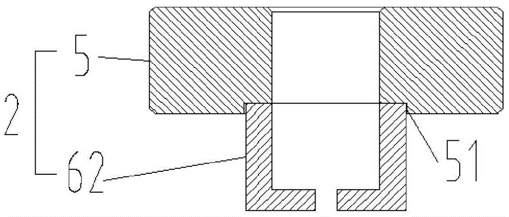
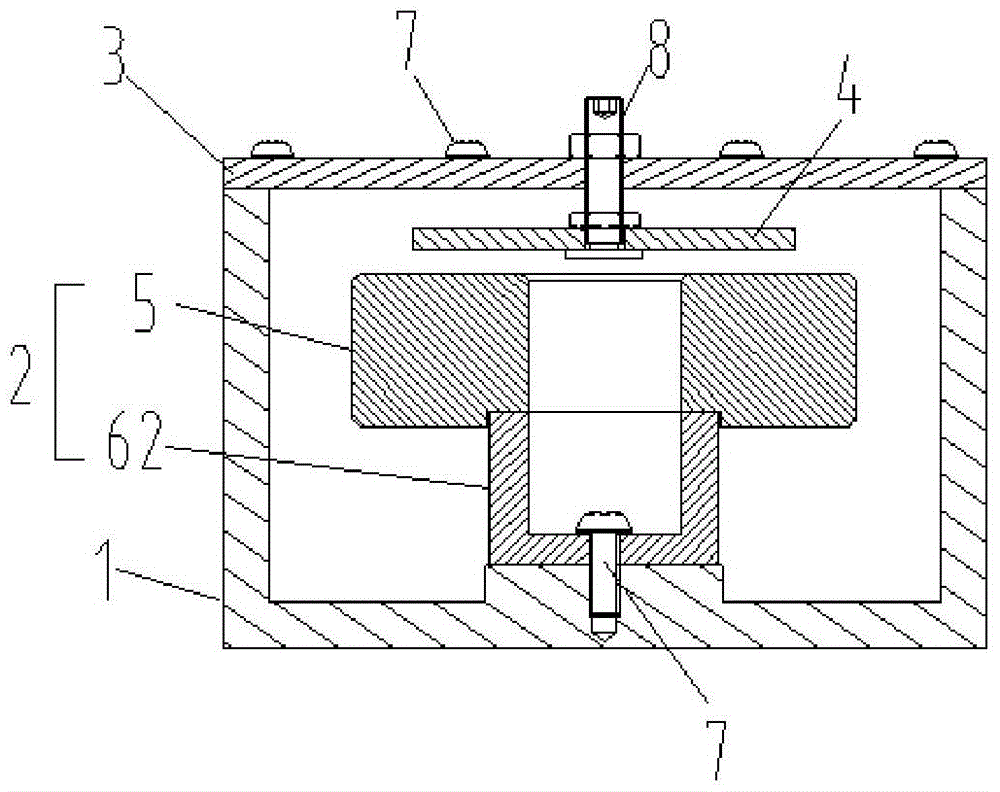
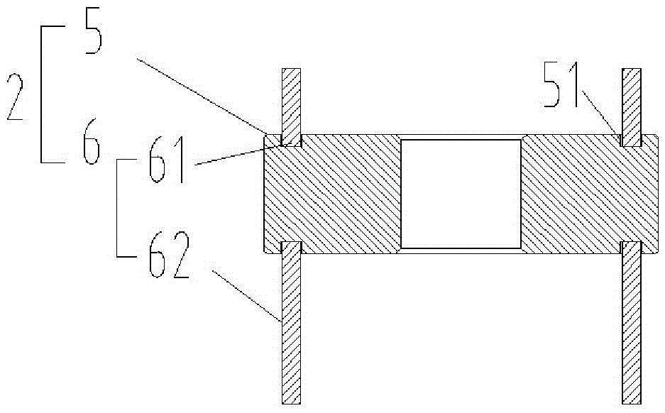
[0058] Such as image 3 , Figure 4 and Figure 5 As shown, the structural diagram of the TE mode dielectric resonator device provided by Embodiment 1 of the present invention includes a cavity 1, a TE01 mode dielectric resonator 2 installed in the cavity 1, and a cover plate 3 mounted on the top of the cavity 1 , a TE01-mode dielectric disk 4 is installed at the bottom of the cover plate 3, and the TE01-mode dielectric resonator 2 is composed of a TE01-mode dielectric resonator rod 5 and a support seat 6 installed thereon. The surface and the bottom surface of the resonant rod 5 are respectively provided with draw-in slots 51, and the upper support base 61 and the lower support base 62 are clamped respectively on the draw-in slots 51, and the lower support base 62 is clamped in the limit groove 11, and the top of the upper support base 61 and the The top of the cavity 1 is arranged horizontally and collinearly. The cover plate 3 includes an inner cover plate 31 and an outer...

Embodiment 2

[0076] This embodiment is a further improvement on the TE mode dielectric resonator device provided in the first embodiment. On the basis of the structure of the first embodiment, the cover plate 3 is connected to the cavity 1 as a whole through six ring-shaped connectors 7 .

Embodiment 3

[0078] This embodiment is a further improvement on the TE mode dielectric resonator device provided in the first embodiment. On the basis of the structure of the first embodiment, the cover plate 3 is integrally connected with the cavity 1 through seven ring-shaped connectors 7 .


PUM


Abstract

The invention provides a TE mode dielectric resonator device. A limiting groove is arranged at the bottom of a cavity; the surface and the underside of a TE01 mode dielectric resonance rod are each provided with a clamping groove; an upper support base and a lower support base are respectively clamped on the clamping groove; the lower support base is clamped in the limiting groove; the top of the upper support base and the top of the cavity are horizontally collinear; a cover plate comprises an inner cover plate and an outer cover plate; a groove is arranged at the bottom of the outer cover plate; an elastic body is arranged in the groove; and the outer cover plate is installed on the inner cover plate through a connecting part. By being supported by the upper and lower support bases, a TE01 mode dielectric resonator is stressed uniformly; the long-term stressed disadvantage of the traditional TE01 mode dielectric resonator while being installed laterally and installed reversely can be solved; due to support through the upper and lower support bases, heat generated by the TE01 mode dielectric resonance rod can be effectively transferred to the cavity and the cover plate, such that heat dissipation of the cavity body is easily carried; and in addition, due to improvement of the cover plate, the problem that the cavity and a TE01 mode medium are in poor contact due to the machining tolerance can be solved.

Description

technical field [0001] The invention relates to the technical field of communication, in particular to a TE mode dielectric resonator device. Background technique [0002] Filters are the main components in electronic equipment, which can filter various power supplies and signals to ensure the stability and reliability of circuit operation. [0003] The filter is an important radio frequency unit in a mobile communication system. In a communication system, filters generally exist between the input and output stages of the active circuit, and each filter has its own different functions. The filter is an indispensable device in the wireless communication system, and its performance is directly related to the communication quality of the entire system. The functions of the filter include: avoiding saturating the receiver front end due to leakage of the output signal at the transmitter; removing interfering signals such as image frequencies; reducing power leakage from the loca...

Claims


Application Information

Patent Timeline
Patent Type & Authority Applications(China)
IPC IPC(8): H01P1/207H01P7/10
CPCH01P1/207H01P7/10
Inventor 崔立成张少林
Owner SUZHOU ZIBO ELECTRONICS TECH CO LTD
Why Eureka
Try Eureka