Visible light communication signal constellation design method, device and system
A visible light communication and signal technology, applied in transmission systems, short-distance systems, electromagnetic wave transmission systems, etc., can solve problems such as inability to achieve system communication performance and optimization
- Summary
- Abstract
- Description
- Claims
- Application Information
AI Technical Summary
Problems solved by technology
Method used
Image
Examples
Embodiment 1
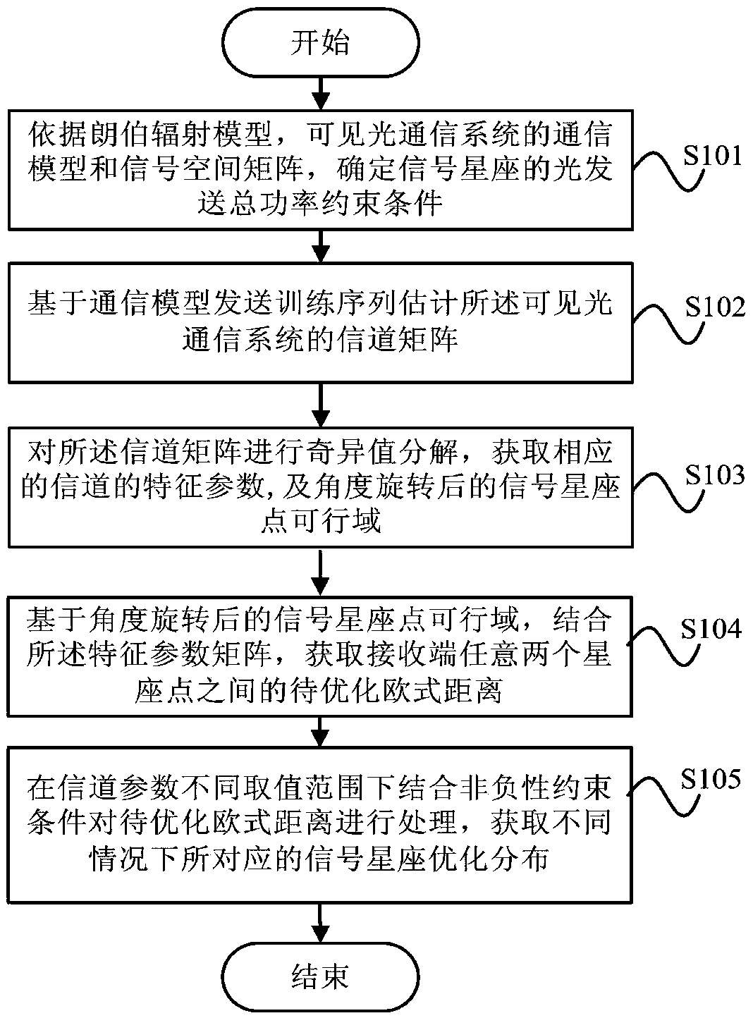
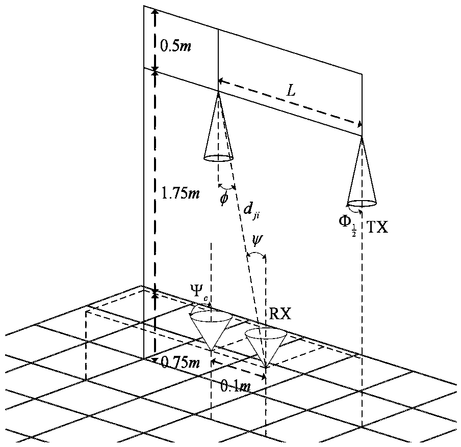
[0078] Such as figure 1 Shown is a flow chart of a visible light communication signal constellation design method disclosed in Embodiment 1 of the present application. This design method is applicable to optical communication systems, especially indoor optical communication systems. In the embodiment of the present application, the figure 2 Shown possesses N t light sources and N r Taking an indoor visible light communication system at a receiving end as an example, the design method mainly includes the following steps:
[0079] Step S101, according to the Lambertian radiation model, the communication model of the visible light communication system and the signal space matrix, determine the total optical transmission power constraint condition of the signal constellation;
[0080] In step S101, based on the 2×N proposed by the embodiment of this application r The communication model under the structure of the optical communication system is shown in formula (3):
[0081] ...
Embodiment 2
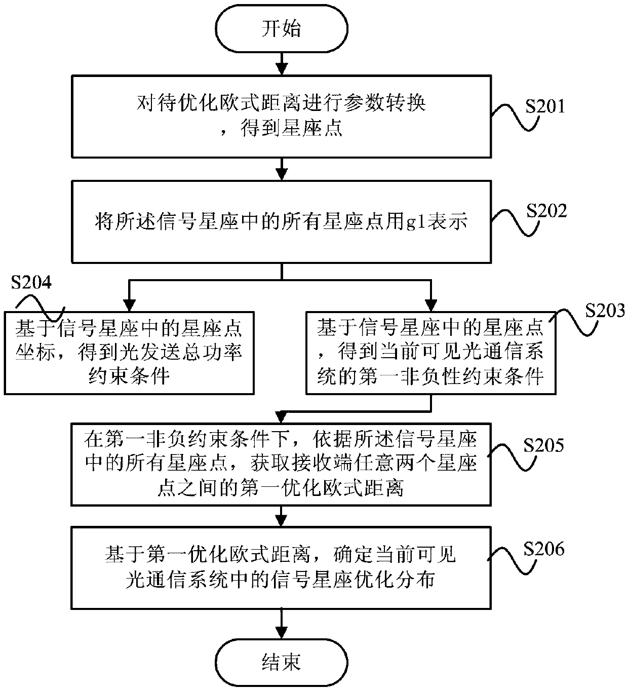
[0108] Based on the above-mentioned Embodiment 1 of the present application, a method for designing a visible light communication signal constellation is disclosed, such as figure 1 The channel characteristic parameter λ shown in 1 , lambda 2 and Under different value ranges of , the Euclidean distance to be optimized is processed in combination with non-negativity constraints, and the step S105 of obtaining the optimal distribution of signal constellations corresponding to different situations is based on different value ranges of channel characteristic parameters, the obtained The optimized distribution of the received signal constellation is different, and the specific execution process is as follows:
[0109] When the channel characteristic parameter λ of the visible light communication system 1 ≥λ 2 >0, Time:
[0110] Such as image 3 As shown, it is a schematic flowchart of the optimal distribution of the signal constellation disclosed in Embodiment 2 of the pre...
Embodiment 3
[0166] Based on the method for designing a visible light communication signal constellation disclosed in Embodiment 1 and Embodiment 2 of the present application, the embodiment of the present application also discloses a visible light communication signal constellation design device and a visible light communication system including the visible light communication signal constellation design device. . The specific structure is as follows.
[0167] Such as Figure 5 As mentioned above, it is a schematic block diagram of the structure of a visible light communication signal constellation design device 10 disclosed in Embodiment 4 of the present application, which mainly includes: a unit 11 for determining the total optical transmission power constraints, a channel matrix acquisition unit 12, and a decomposition unit 13, to be optimized Euclidean distance acquisition unit 14 and optimized distribution unit 15 .
[0168] Among them, the optical transmission total power constrai...
PUM
 Abstract
Description
Claims
Application Information
 - R&D
- Intellectual Property
- Life Sciences
- Materials
- Tech Scout
- Unparalleled Data Quality
- Higher Quality Content
- 60% Fewer Hallucinations
Browse by: Latest US Patents, China's latest patents, Technical Efficacy Thesaurus, Application Domain, Technology Topic, Popular Technical Reports.
© 2025 PatSnap. All rights reserved.Legal|Privacy policy|Modern Slavery Act Transparency Statement|Sitemap|About US| Contact US: help@patsnap.com


