Connecting structure for electronic cabinet backboard and connector

A technology for connecting structures and connecting parts, which is applied in electrical components, cabinets/cabinets/drawer parts, electrical equipment shells/cabinets/drawers, etc. The surface can not meet customer requirements and other problems, to achieve the effect of easy assembly and reasonable structure

Inactive Publication Date: 2016-05-04
LEKAI TECH SUZHOU
View PDF3 Cites 0 Cited by
  • Summary
  • Abstract
  • Description
  • Claims
  • Application Information

AI Technical Summary

Problems solved by technology

[0002] The back panel of the electronic cabinet is connected to the bracket through the connector, and the connector is welded on the inner surface of the back panel of the electronic cabinet. After welding, electroplating is required, but after the connector is welded to the back panel of the electronic cabinet, the inner surface of the back panel of the electronic cabinet is closely attached to the connector Rely, the inner surface of the electronic cabinet backplane is close to the area (that is, the inner surface of the electronic cabinet backplane and the joint is close to the joint area) and the joint is basically no gap, so that the pickling solution flowing to the joint area during electroplating Unable to discharge, corrode the substrate, and the appearance of the product cannot meet customer requirements

Method used


Image

  • Connecting structure for electronic cabinet backboard and connector

Examples


Embodiment Construction

[0020] The specific embodiments of the present invention will be further described below in conjunction with the drawings and embodiments. The following embodiments are only used to explain the technical solutions of the present invention more clearly, and cannot be used to limit the protection scope of the present invention.

[0021] The technical scheme of the present invention is:

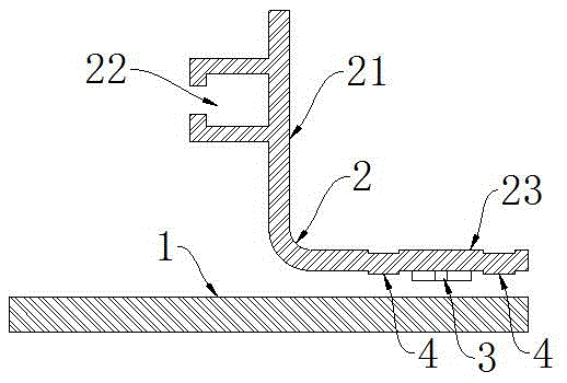
[0022] Such as figure 1 As shown, a connection structure of an electronic cabinet backplane 1 and a connector 2 includes a rectangular metal backplane 1 and a connector 2;

[0023] The connecting piece 2 is a profile, and the connecting piece 2 includes the following edges extending along the longitudinal direction of the profile: a connecting edge 21 for connecting the bracket, which is provided on the connecting edge 21 and extends in the same direction as the connecting edge 21. Groove 22, and abutting edge 23 for abutting against the inner surface of the metal panel;

[0024] The connecting edge 2...


PUM


Abstract

The invention discloses a connecting structure for an electronic cabinet backboard and a connector. The connecting structure comprises a rectangular metal backboard and the connector, wherein the connector is a profile and comprises a connecting side, an inserting groove and a butting side; the connecting side is used for connecting a bracket; the inserting groove is arranged on the connecting side and extends in the same direction as the connecting side; the butting side is used for being butted with the inner surface of a metal panel; two cross convex hulls and a plurality of bumps are stamped on the butted surface, butted with the inner surface of the backboard, of the butting side; two cross oval countersunk holes which are matched with the cross convex hulls in a manner of one-to-one correspondence are arranged on the inner surface of the backboard; each cross convex hull is inserted into the corresponding cross oval countersunk hole; the bumps are directly butted with the inner surface of the backboard; the butting side and the inner surface of the backboard are fixed through welding of a plurality of welding spots; and the welding spots are evenly distributed along the outer edge of the butting side. The connecting structure for the electronic cabinet backboard and the connector is reasonable, convenient to assemble and suitable for electroplating.

Description

Technical field [0001] The invention relates to a connection structure between an electronic cabinet backplane and a connector. Background technique [0002] The back panel of the electronic cabinet is connected to the bracket through the connector. The connector is welded to the inner surface of the back panel of the electronic cabinet. After welding, electroplating is required. However, after the connector is welded to the back panel of the electronic cabinet, the inner surface of the back panel of the electronic cabinet closely adheres to the connector. Lean, the contact area on the inner surface of the back panel of the electronic cabinet (that is, the contact area where the inner surface of the back panel of the electronic cabinet is attached to the connector) and the connector are basically free of gaps, resulting in the pickling liquid flowing to the abutment area during electroplating It cannot be discharged, corrodes the substrate, and the appearance of the product fails...

Claims


Application Information

Patent Timeline
Patent Type & Authority Applications(China)
IPC IPC(8): H05K5/02
CPCH05K5/0217
Inventor 乐钰铭
Owner LEKAI TECH SUZHOU
Why Eureka
Try Eureka