
Comminuting device

A technology of equipment and pulverizing chamber, which is applied in the field of metal-containing slag and other material mixtures, can solve the problems of increased grinding and pulverizing impact and pulverizing load, and achieve a significant separation effect.

Active Publication Date: 2016-05-04
PMS HANDELSKONTOR
View PDF8 Cites 6 Cited by
  • Summary
  • Abstract
  • Description
  • Claims
  • Application Information

AI Technical Summary

Problems solved by technology

In order to release smaller metal particles through this mill, very small gap spacings, e.g. below 20mm, have to be set, which can then lead to a drastic increase in grinding crushing relative to impact crushing loads
This grinding comminution results in the soft non-ferrous metal being ground so that it can no longer be separated by the non-ferrous metal separator
Small metal particles that are present in the slag in a pure form can therefore only be recovered to a limited extent by comminution plants according to the prior art

Method used


Image

  • Comminuting device
  • Comminuting device

Examples


Embodiment Construction

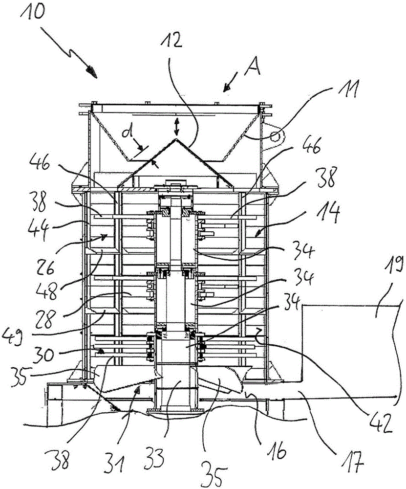
[0059] figure 1 A material comminution and separation device 1 is shown having an inlet hopper 11 and a feed cone 12 arranged below the inlet hopper, which feed cone 12 is arranged on a cylindrical comminution chamber 14 . The gap d between the inlet funnel 11 and the feed cone 12 can be adjusted in the direction of the cylinder axis of the crushing chamber by a height adjuster (not shown) of the inlet funnel. Both the inlet hopper and the feed cone result in a controlled, uniform delivery of material throughout the active area of ​​the comminution device (ie the entire 360° fill area of ​​the cylindrical comminution chamber) without damaging or wearing down components of the comminution device. Below the comminution chamber there is a horizontal distribution floor 16 , from which a channel 17 leads into a rest chamber 19 . The inlet funnel 11, feed cone 12, crushing chamber 14 and distribution floor 16 are connected to each other and rest on figure 1 on the frame 18 shown s...


PUM


Abstract

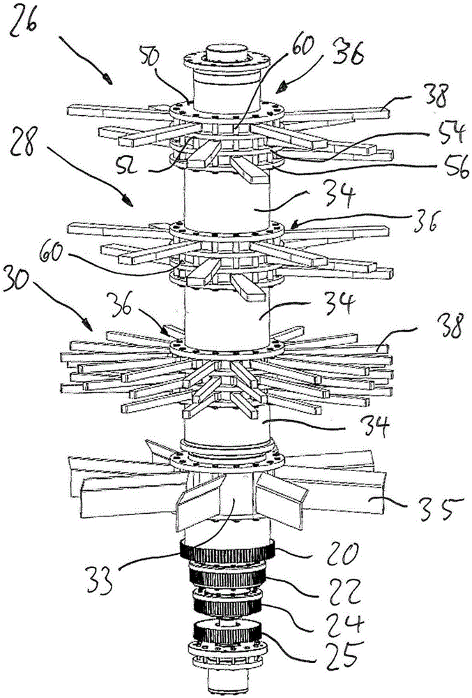
The invention relates to a device (10) for mechanically comminuting material conglomerates composed of materials having different density and / or consistency, comprising a comminuting chamber (14) having a feed side and an outlet side, which comminuting chamber is surrounded by an in particular circular cylindrical and / or conical comminuting chamber wall (42) expanded in a downward direction and has at least two segments which are consecutive in an axial direction, in each of which at least one rotor (26, 28, 30) is arranged coaxially to the comminuting chamber, wherein each rotor has a rotor shaft and has striking tools (38) extending at least largely radially into the comminuting chamber at least during operation, a feeding cone (12), which covers the rotor shaft(s), is arranged above the comminuting chamber (14) on the feed side, and an inflow funnel (11) is arranged above the feeding cone (12), wherein an inflow region is formed between the inflow funnel and the feeding cone, the size (d) of which inflow region can be adjusted, the directions of rotation of the rotors (26, 28, 30) are opposite in at least two consecutive segments, discharge ribs (48) are arranged annularly on the inside of the comminuting chamber wall at axial distances and / or the radius of the comminuting chamber wall (42) increases from top to bottom, and an air flow apparatus (17, 72) for leading a particle / air mixture out of the comminuting chamber (14) is arranged in connection with the comminuting chamber, which air flow apparatus has at least one fan rotor (31) arranged coaxially to the rotor axis, the at least one fan rotor having a dedicated shaft (33), which is driven by means of a dedicated fan drive (25) in order to rotate the fan rotor independently of the rotors. Very high impact energies of material conglomerates to be separated against the striking tools are achieved by means of such a device, wherein the smashed particles can be effectively transferred into a further processing stage. In addition, the material separation can be controlled by means of the effective control of the material flow, in particular the flow of very fine particles.

Description

technical field [0001] The invention relates to a crushing or stripping plant, in particular for metal and mineral material compounds in ore sands (mining), metal-containing industrial slags, metal-containing slags for thermal waste utilization and other material mixtures. Mineral sands are known to contain various metal and mineral material compounds, which can only be separated from the corresponding mineral sands with great difficulty according to the current state of the art. Background technique [0002] Efficient extraction of metals is greatly simplified by integrally stripping or separating all materials in the ore. During the smelting of metals, due to the melting process, it is inevitable that molten metals such as Fe and Cu enter the slag, and these are also difficult to recover. [0003] In slags and ashes of thermal waste utilization as well as in metal production slags there are large quantities of ferrous and non-ferrous metals, which are doped in pure form o...

Claims


Application Information

Patent Timeline
Patent Type & Authority Applications(China)
IPC IPC(8): B02C13/16B02C13/282B02C13/288
CPCB02C13/282B02C13/286B02C13/288B02C2013/28672B02C13/16Y02P10/20B02C13/14B02C13/10B02C13/18
Inventor F·沙佛
Owner PMS HANDELSKONTOR
Learn More