Method for supplying a control device

A technology of control device and power supply circuit, applied in the direction of transmission control, components with teeth, belt/chain/gear, etc., can solve the problem that the braking mode cannot be maintained for a long time, and achieves simple diagnosability and simplified structure. Effect

Active Publication Date: 2016-05-04
SCHAEFFLER TECH AG & CO KG
View PDF8 Cites 0 Cited by
  • Summary
  • Abstract
  • Description
  • Claims
  • Application Information

AI Technical Summary

Problems solved by technology

[0007] The disadvantage here is that the braking mode cannot be perma

Method used


Image

  • Method for supplying a control device

Examples


Embodiment Construction

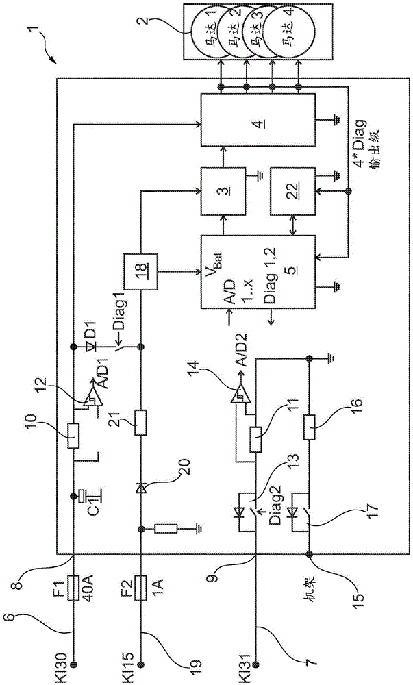
[0023] according to figure 1 , the control device 1 operates an actuator 2 comprising a plurality of electric motors to operate a parallel shift transmission comprising two friction clutches. For the sake of overview, the lines and components for controlling the actuator and supplying current to the actuator have been omitted. Only one driver 3 and output stage 4 are shown schematically. A logic module 5 in the form of a microprocessor located at terminal GND takes over the control and calculation processes of the control device 1 .

[0024] The control device 1 is connected by means of a first current-carrying line 6 to the on-board electrical system of the motor vehicle, in particular to the so-called “terminal 30 ” (battery positive input). The ground line 7 belonging to the first line 6 conducting the current is connected to the so-called "terminal 31" (feedback line to battery negative or ground). The control device 1 is supplied with energy by means of the lines 6 , 7...


PUM


Abstract

The invention relates to a method for maintaining a safe driving state of a motor vehicle by an actuator which is driven by a control device (1), wherein the control device (1) is connected to an external energy supply via a current-carrying supply line (6) and the voltage across the supply line (6) is measured, wherein a second current-carrying line (19) for supplying the control device (1) is activated when an undervoltage is identified on the supply line (6). In a method in which structural expenditure and costs are reduced, a current-carrying line (19) which is present in the motor vehicle in any case is used as the second current-carrying line for supplying a logic module (5), which is contained in the control device (1), in order to permanently maintain an emergency state of the motor vehicle.

Description

technical field [0001] The invention relates to a method for maintaining a safe driving state of a motor vehicle by means of an actuator according to the preamble of claim 1 and a method for carrying out the method according to the preamble of claim 4 control device. [0002] The invention relates to a method for maintaining a safe driving state of a motor vehicle by means of an actuator which is controlled by a control device, wherein the control device is connected to an external energy supply via a current-carrying power supply line and measures the voltage on the power supply line Voltage, wherein a second current-carrying line is activated for supplying a control device when it is determined that the voltage on the supply line is low, and a control device for carrying out the method. Background technique [0003] Such a control device can be used, for example, in an automatically shifted transmission in a motor vehicle. The automatic shift transmission can be, for exa...

Claims


Application Information

Patent Timeline
IPC IPC(8): F16H61/12
Inventor 于尔根·格哈特马丁·齐默尔曼
Owner SCHAEFFLER TECH AG & CO KG
Why Eureka
Try Eureka