Numerical control high-speed carving and milling machine of bridge type elevated cross beam moving gantry

A beam, high-speed technology, applied in the field of machine tools, can solve the problems of inaccurate feed of each axis, and achieve the effects of compact structure, improved stability, and improved kinematic rigidity

Active Publication Date: 2016-05-11
南京诚友数控设备有限公司
View PDF5 Cites 1 Cited by
  • Summary
  • Abstract
  • Description
  • Claims
  • Application Information

AI Technical Summary

Problems solved by technology

[0003] The purpose of the present invention is to provide a CNC bridge-type elevated beam mobile gantry high-speed engraving and milling machine to solve the technical defect of inaccurate feed of each axis in the prior art

Method used


Image

  • Numerical control high-speed carving and milling machine of bridge type elevated cross beam moving gantry
  • Numerical control high-speed carving and milling machine of bridge type elevated cross beam moving gantry
  • Numerical control high-speed carving and milling machine of bridge type elevated cross beam moving gantry

Examples


Embodiment 1

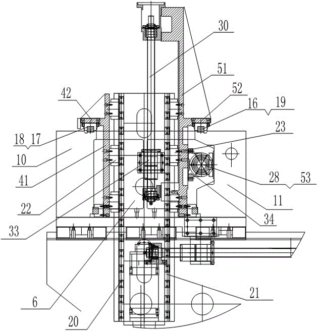
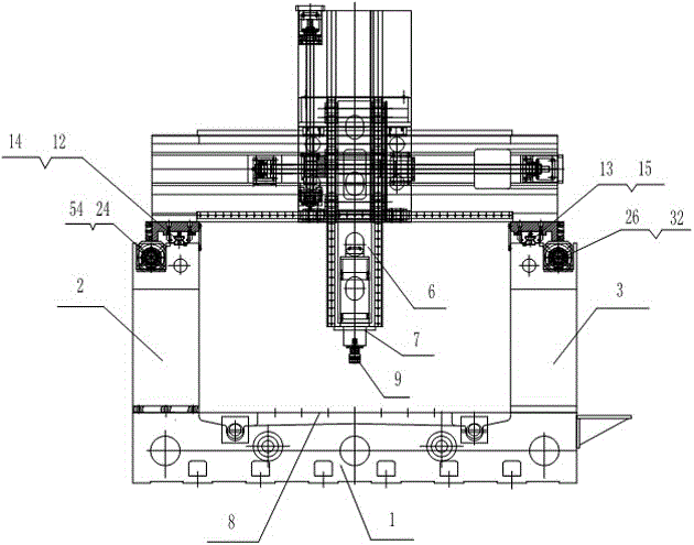
[0047] Such as figure 1 , figure 2 , image 3 with Figure 4 The CNC bridge-type elevated crossbeam mobile gantry high-speed engraving and milling machine shown includes a base 1, a left wall 2, a right wall 3, a beam, a front slide, a rear slide, a ram 6 and a spindle 7; the base 1 A workbench 8 is arranged on the top, the left wall 2 and the right wall 3 are arranged on the base 1 in parallel and the workbench 8 is located between the left wall 2 and the right wall 3, and the crossbeam is composed of a front crossbeam 10 and a rear crossbeam 11, the cross-section of the front cross beam 10 is "one" shape, the rear cross beam 11 is "Π" shape and the opening faces forward, and one end of the front cross beam 10 is fixed to one end of the rear cross beam 11.

[0048] The two ends of the beam are respectively arranged on the left wall 2 and the right wall 3, and form a horizontal movement pair with the left wall 2 and the right wall 3 respectively; the front sliding seat and...

Embodiment 2

[0060] Such as Figure 5 with Image 6As shown, the difference between this embodiment and Embodiment 1 is that the dual-drive engraving and milling is realized in the up and down direction. Compared with Embodiment 1, the structural difference is that the base 1, the left wall 2, the right wall 3, the Except for the guide rail 12, the right guide rail 13 and the workbench 8, the remaining components are two sets with the same structure. The specific structure is that two beams are slidably installed on the left guide rail 12 and the right guide rail 13, and the sliding methods are the same as those in the first embodiment. , not detailed here.


PUM


Abstract

The invention discloses a numerical control high-speed carving and milling machine of a bridge type elevated cross beam moving gantry. The numerical control high-speed carving and milling machine comprises a base, a left wall, a right wall, a cross beam, a front sliding seat, a rear sliding seat, a ram and a spindle. A workbench is arranged on the base, the left wall and the right wall are arranged on the base in parallel, and the workbench is located between the left wall and the right wall. The two ends of the cross beam are arranged on the left wall and the right wall, and horizontal moving pairs are formed by the two ends of the cross beam, the left wall and the right wall. The front sliding seat and the rear sliding seat are arranged in parallel, a horizontal moving pair is formed by the front portion of the front sliding seat and the cross beam, and a horizontal moving pair is formed by the rear portion of the rear sliding seat and the cross beam. The ram is located between the front sliding seat and the rear sliding seat, a vertical moving pair is formed by the front portion of the ram and the front sliding seat, and a vertical moving pair is formed by the rear portion of the ram and the rear sliding seat. The spindle is arranged on the lower portion of the ram and used for being provided with a carving and milling cutter. The numerical control high-speed carving and milling machine has the beneficial effects that due to the fact that the cross beam in the machine is supported by the left wall and the right wall, the down milling precision and the up milling precision of a workpiece are the same.

Description

technical field [0001] The invention relates to a numerically controlled bridge-type elevated beam moving gantry high-speed engraving and milling machine, which belongs to the technical field of machine tools. Background technique [0002] In the past two decades, after the introduction of CNC technology in my country's metal cutting machine tools, the quality and efficiency of metal cutting processing have been greatly improved. CNC metal cutting machine tools have almost completely replaced ordinary metal cutting machine tools. With the rapid development of computer technology, CNC machining technology is also constantly improving. At present, it is difficult for ordinary domestic CNC engraving and milling machines to keep up with the processing requirements of some high-precision products in terms of processing accuracy, processing speed and processing adaptability. More stable, more accurate and sensitive high-speed engraving and milling machine. Contents of the inven...

Claims


Application Information

Patent Timeline
Patent Type & Authority Applications(China)
IPC IPC(8): B23C1/06B23Q1/01
CPCB23C1/06B23Q1/012
Inventor 朱志逊朱传霖
Owner 南京诚友数控设备有限公司
Why Eureka
Try Eureka