tig welding torch

A technology of welding torches and supports, applied in the field of TIG welding torches, can solve problems such as complex structures and achieve cost-saving effects

Active Publication Date: 2018-10-09
FRONIUS INTERNATIONAL GMBH
View PDF6 Cites 0 Cited by
  • Summary
  • Abstract
  • Description
  • Claims
  • Application Information

AI Technical Summary

Problems solved by technology

Its construction is relatively complex and large, which makes it unsuitable for all workpiece geometries, especially for deposition welding inside tubes

Method used


Image

  • tig welding torch
  • tig welding torch
  • tig welding torch

Examples


Embodiment Construction

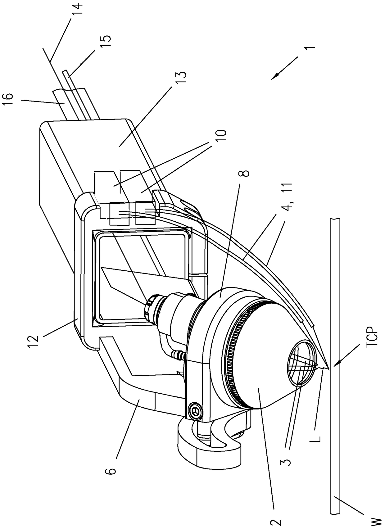
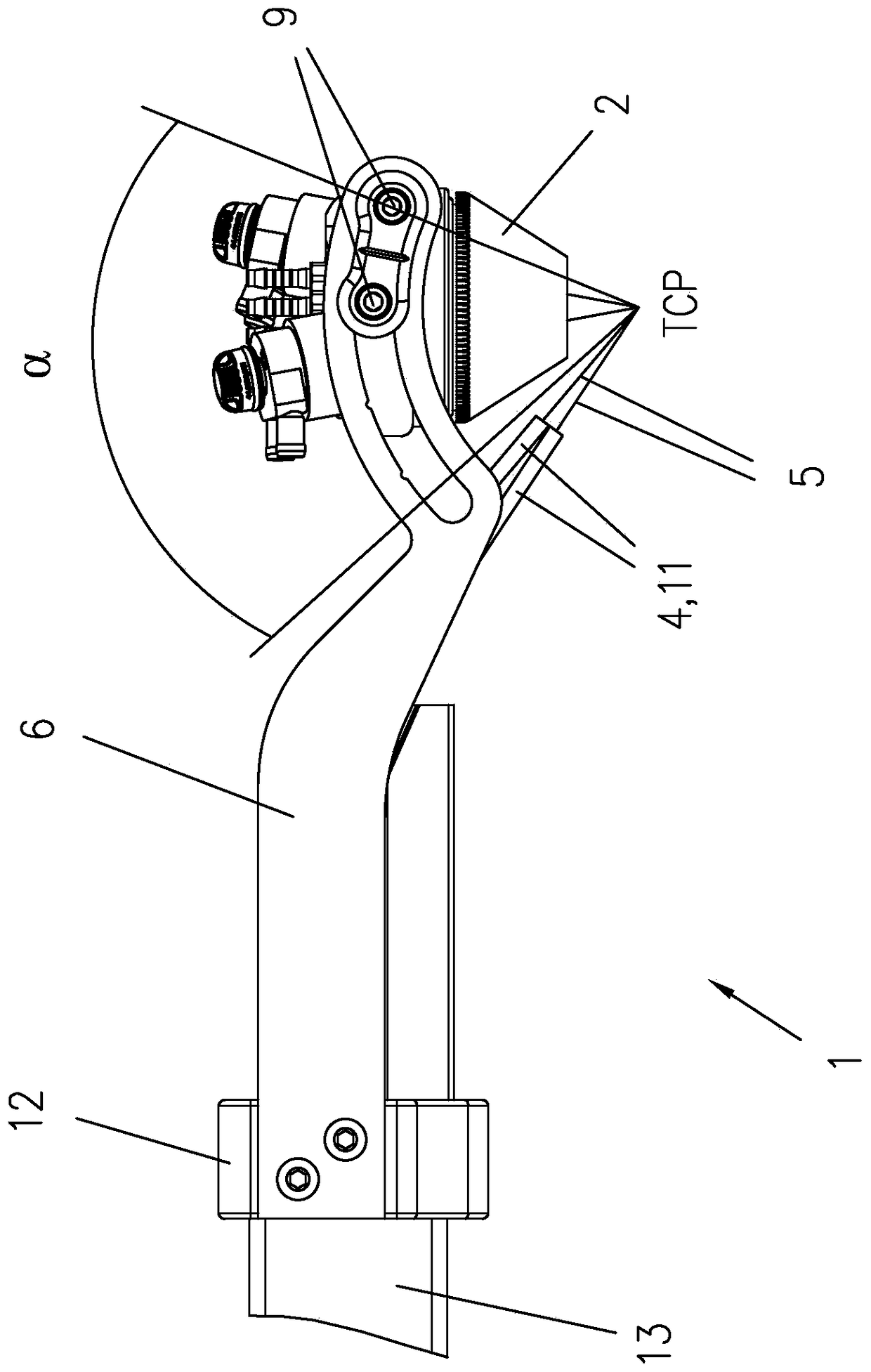
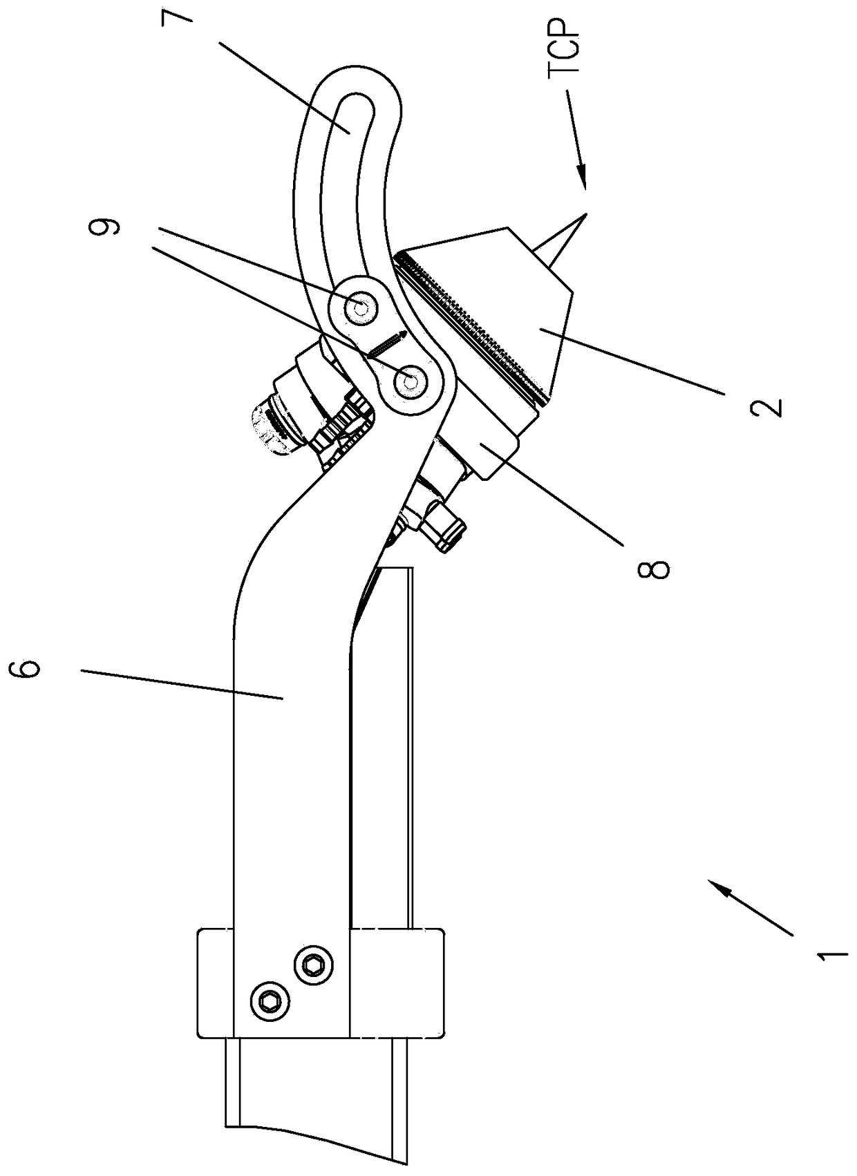
[0020] figure 1 A perspective view of one embodiment of a TIG welding torch 1 is shown. The TIG welding torch 1 comprises a torch head 2 in which at least one (preferably two) non-melting electrodes 3 are arranged, preferably non-melting tungsten electrodes. The non-fused electrode 3 is connected to a welding power source (not shown) through a suitable cable 14 so that the electrode 3 can be supplied with a suitable current. Commonly used shielding gases (argon, helium, etc.) are delivered to the welding point via the gas supply line 15 . Between the at least one non-melting electrode 3 and the workpiece W to be treated, an electric arc L is ignited, which melts at the tool center point (TCP) at least one thread-like filler material 5 conveyed by the feed device 4 so that, for example, in the molten The molten filler material 5 is applied to the surface of the workpiece W during deposition (or deposition) welding. The longitudinal axis of each electrode 3 and the longitudin...


PUM


Abstract

The invention relates to a TIG welding torch (1) comprising a torch head (2) with at least one non-melting electrode (3) and at least one feeder device (4) for a melting wire-shaped filler material (5), wherein the longitudinal axis of each electrode (3) and the longitudinal axis of each wire-shaped filler material (5) intersect each other in a Tool Center Point (TCP), and wherein the torch head (2) is arranged adjustably on a support (6) and is adapted to be fixed in at least two different positions while the Tool Center Point (TCP) remains the same. For achieving a compact construction and higher flexibility during welding, the support (6) is of elongate and quasi V-shaped design and comprises a circular guide (7) at the front end thereof, in which guide (7) a slide (8) connected with the torch head (2) is adapted to be arranged, so that the outer dimensions of the torch head (2) are not changed substantially in the case of an adjustment of the torch head (2).

Description

technical field [0001] The present invention relates to a TIG welding torch comprising: a welding torch head having at least one non-melting electrode; and at least one feeding device for molten wire-like filler material, wherein the longitudinal direction of each electrode axis and the longitudinal axis of each filamentary filler material intersect each other at a tool center point (TCP), and wherein the torch head is adjustably mounted on the support and adapted to be fixed in at least two different positions, and The tool center point (TCP) remains constant. Background technique [0002] TIG (tungsten inert gas) welding torches comprise at least one (preferably two) non-melting refractory tungsten electrodes in order to form an arc burning between the electrodes and the workpiece to be treated. The material for filling the gap between two workpieces or for being applied on the surface of the workpieces during so-called deposition welding is supplied by a thread-like fill...

Claims


Application Information

Patent Timeline
Patent Type & Authority Patents(China)
IPC IPC(8): B23K9/28B23K9/167
CPCB23K9/29B23K9/167B23K9/28B23K9/296B23K9/126
Inventor 曼弗雷德·许宾格约瑟夫·莱布斯蒂芬·皮林格尔
Owner FRONIUS INTERNATIONAL GMBH
Why Eureka
Try Eureka