Micro-strip open loop filter

A filter and microstrip technology, applied in waveguide devices, electrical components, circuits, etc., can solve the problems of high resonance frequency, large size, high order, etc., to reduce the resonance frequency, extend the current path, and extend the current path Effect

Inactive Publication Date: 2016-12-07
CHENGDU UNIV OF INFORMATION TECH
View PDF4 Cites 2 Cited by
  • Summary
  • Abstract
  • Description
  • Claims
  • Application Information

AI Technical Summary

Problems solved by technology

At present, most of the quasi-elliptic function filtering characteristics are realized by cross-coupling filters, but traditional cross-coupling filters have the disadvantages of higher order, higher resonance frequency, and larger size.

Method used


Image

  • Micro-strip open loop filter
  • Micro-strip open loop filter
  • Micro-strip open loop filter

Examples


Embodiment 1

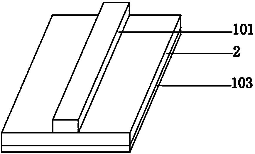
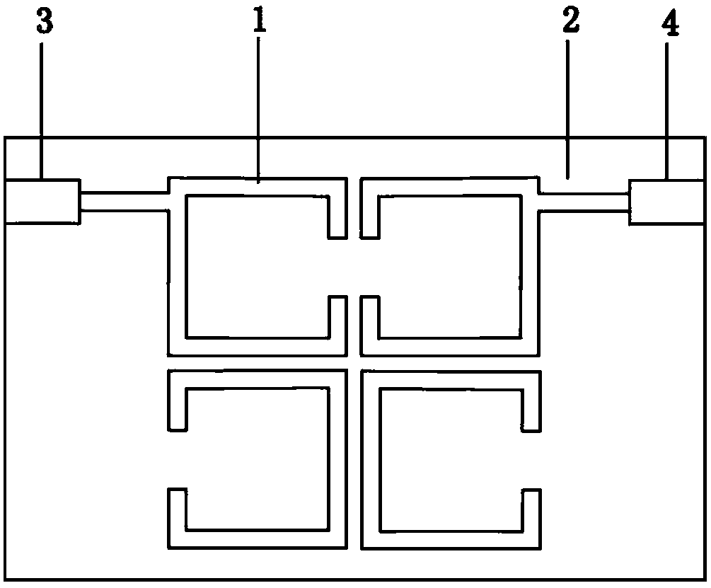
[0026] Such as Figure 5 As shown, the microstrip open-loop filter includes a ground plane 103 located on the back of the dielectric substrate 2 and an input terminal 3, an input terminal microstrip line 5, an output terminal 4, an output terminal microstrip line 6 and a Two square resonator groups, each resonator group includes two sub-resonators 1, and the four sub-resonators 1 are all open-loop structures with the same size and structure. The two sub-resonators 1 in the first resonator group in the first row are arranged in a straight line with the input end 3 and the output end 4 and are symmetrically distributed with the mid-perpendicular line of the line as the axis of symmetry, and the two resonator groups are connected to each other. Parallel and the sub-resonators 1 in each resonator group are distributed symmetrically with the mid-perpendicular line as the axis of symmetry. The output terminal 3 is coupled and connected to the sub-resonator 1 close to the input term...

Embodiment 2

[0029] Such as Image 6As shown, compared with the microstrip open-loop filter of Embodiment 1, the main difference is that the microstrip open-loop filter of this embodiment includes two resonator groups, wherein the first resonator group includes four sub-resonators 1. The second resonator group includes two sub-resonators 1 .

Embodiment 3

[0031] Such as Figure 7 As shown, compared with the microstrip open-loop filter of Embodiment 1, the main difference is that the microstrip open-loop filter of this embodiment includes three resonator groups, wherein the first resonator group includes two sub-resonators 1. The second resonator group includes four sub-resonators 1, and the third resonator group includes two sub-resonators 1.


PUM


Abstract

The invention relates to a microstrip open loop filter. The microstrip open-loop filter includes a ground plane mounted on the back surface of a dielectric substrate and an input end, an output end and at least one resonator group mounted on the front surface of the dielectric substrate. The resonator group comprises n square or rectangular sub-resonators wherein represents at least two and a multiple of two. All of the n sub-resonators are provided with an opening structure whose size and structure are identical. The n sub-resonators, the input end and the output end are arranged in a straight line and are distributed symmetrically with the vertical line of the straight line being their symmetry axis. The two edges of each sub-resonator are provided with an opening respectively. The openings divide each sub-resonator into a first half ring and a second half ring. Each sub-resonator is provided with a microstrip support line to have the first half ring and the second half ring connected. The adding of a microstrip support line into the rings apparently extends the path of current, effectively reduces the resonant frequency of the sub-resonator and helps facilitate the small scale of a filter. At the same time, the two openings mounted on the rings of a sub-resonator further extend the path of current.

Description

technical field [0001] The invention relates to a microstrip open-loop filter. Background technique [0002] Microwave filters play a very important role in wireless signal processing, which can filter out interference signals and pass useful signals. In the field of microwave filters, microstrip line systems are usually used, and their structures are as follows figure 1 As shown, it includes a signal layer 101 at the top layer, a dielectric substrate 2 at the middle layer, and a ground layer 103 at the bottom layer. The ground layer 103 is generally made of metal material, which may be metal foil or metal coating, and the signal layer 101 is a microstrip line. The existing microstrip filter uses an open-loop resonator (a resonator is a microstrip line with a specific length and capable of resonating), and the resonator is connected to the input / output terminal in a tapped or coupled manner. [0003] At present, microstrip filters with quasi-elliptic function responses ar...

Claims


Application Information

Patent Timeline
Patent Type & Authority Applications(China)
IPC IPC(8): H01P1/203
CPCH01P1/20381
Inventor 夏运强
Owner CHENGDU UNIV OF INFORMATION TECH
Why Eureka
Try Eureka