Mold stripping structure of injection mold

An injection mold and demoulding technology, which is applied in the field of plastic processing, can solve the problems of reducing the production efficiency of injection molding products, unfavorable mold reassembly, etc., and achieve the effects of maintaining completeness, saving energy, and reducing force

Active Publication Date: 2016-05-11
浙江诺格汽车模具有限公司
View PDF5 Cites 0 Cited by
  • Summary
  • Abstract
  • Description
  • Claims
  • Application Information

AI Technical Summary

Problems solved by technology

In the prior art, most injection molds include a fixed mold and a movable mold, and may also have a forming rod. In general, in order to ensure the integrity of the product, the staff often One by one, the parts of the mold are removed in order, which greatly reduces the production efficiency of injection molding products, and is also not conducive to the reassembly of the mold

Method used


Image

  • Mold stripping structure of injection mold
  • Mold stripping structure of injection mold
  • Mold stripping structure of injection mold

Examples


Embodiment 1

[0048] The blind hole on the fixed sleeve 15 is provided with internal threads, and the forming rod 13 is provided with external threads. The mutual connection is realized through the cooperation of threads between the fixed sleeve 15 and the forming rod 13, so that the fixing is more firm on the one hand, and the dismounting is also easier. Convenient, and after the installation of the forming rod 13 and the fixing sleeve 15 is completed, the length of the forming rod 13 entering the fixing sleeve 15 is slightly greater than half of the entire length of the forming rod 13, so that the active area of ​​the fixing sleeve 15 on the forming rod 13 can be larger, It is beneficial for the forming rod 13 to be separated from the finished product, and it is not easy to cause the forming rod 13 to break.

Embodiment 2

[0050] The cross-section of the rod head of the molding rod 13 is elliptical, and the blind hole opening of the fixed sleeve 15 is also elliptical, and matches the rod head of the molding rod 13, and the bottom of the blind hole is a circular groove, and the circle The radius of the shaped groove is equal to the major semi-axis of the blind hole opening, and the thickness is equal to the rod head of the forming rod 13, so as long as the rod head of the forming rod 13 is installed in the circular groove along the direction of the blind hole opening, rotate 90 ° just can form bar 13 and fixing sleeve 15 to be firmly fixed together. The disassembly process can be carried out along the reverse process.

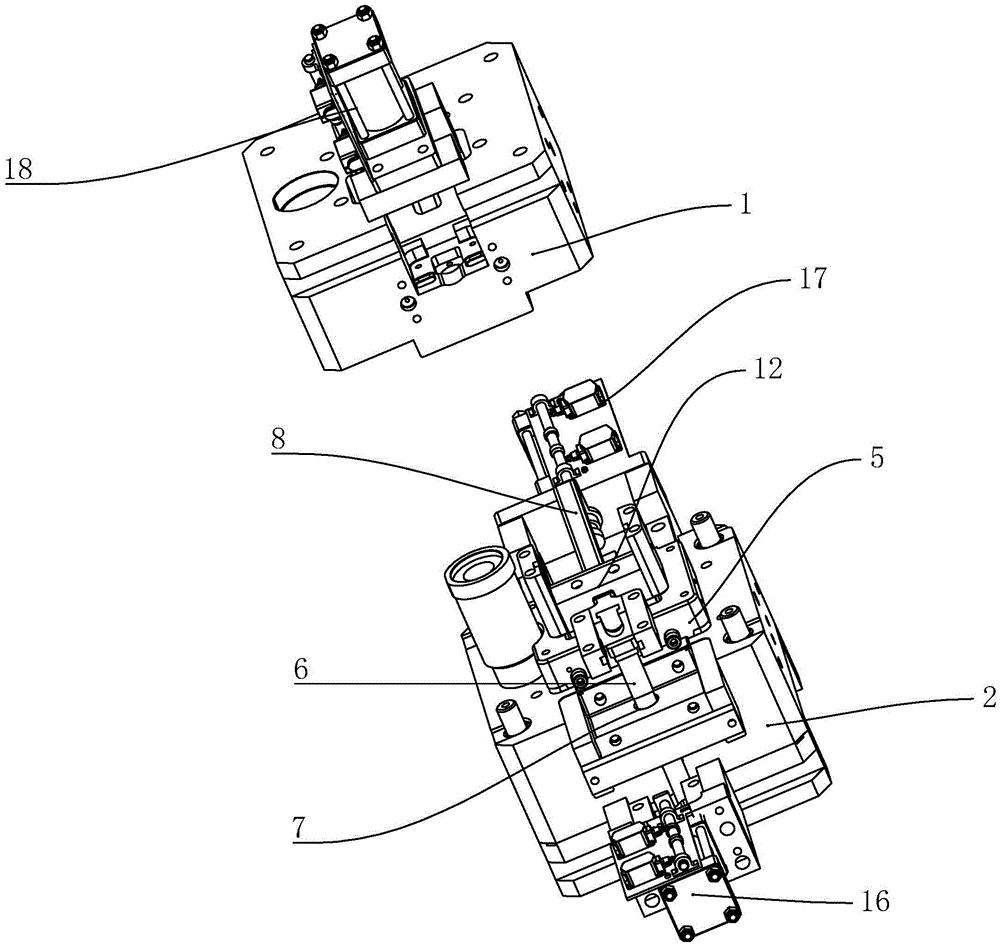
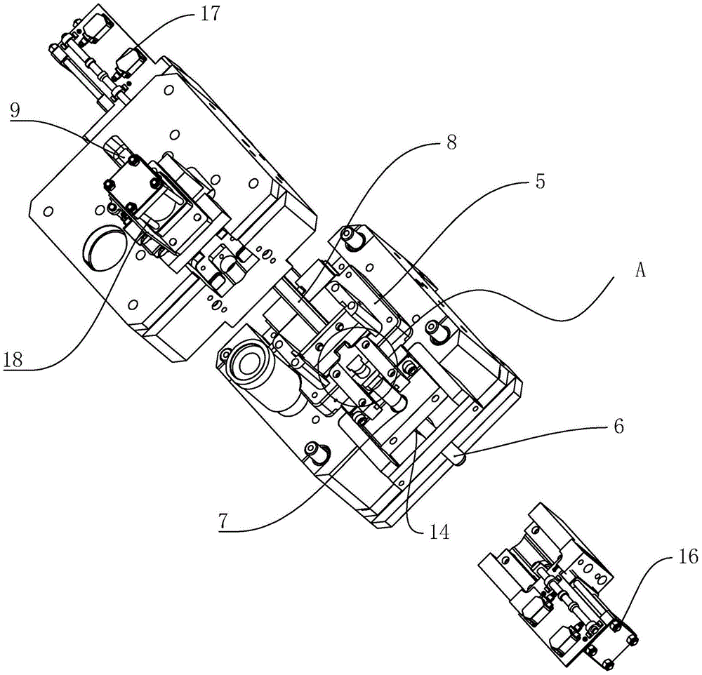
[0051] A further solution is that the first power unit 16 is connected to the side of the horizontal section 81 away from the second fixed mold core 4, the upper movable block 12 is connected with the third power unit 18 along the forming rod 13, and the second fixed mold core 4 d...


PUM


Abstract

A mold stripping structure of an injection mold comprises a fixed mold and a movable mold. The fixed mold comprises a first fixed mold core, a second fixed mold core and a fixed mold base. The first fixed mold core and the second fixed mold core are embedded in the fixed mold base. A through hole for allowing penetration of an inclined guide column is formed in one side, back on to the second fixed mold core, of the first fixed mold core. The inclined guide column is abutted against the movable mold. A guide rod is arranged above the first fixed mold core and comprises a horizontal section and an inclined section. The lower surface of the horizontal section is fixed to the top of the inclined guide column. A movable block capable of moving along the inclined section sleeves the inclined section and can move on the inclined section. A forming rod is arranged below the movable block. The inclined guide column can drive the first fixed mold core and the forming rod to be separated from a product during mold stripping, so that mold stripping efficiency is improved greatly, mold stripping steps are reduced, and product integrity is improved.

Description

technical field [0001] The invention relates to the field of plastic processing, in particular to a demoulding structure of an injection mold. Background technique [0002] Injection mold is a tool for producing plastic products; it is also a tool for giving plastic products complete structure and precise dimensions. In the prior art, most injection molds include a fixed mold and a movable mold, and may also have a forming rod. In general, in order to ensure the integrity of the product, the staff often One by one, the parts of the mold are removed in sequence, which greatly reduces the production efficiency of injection molding products, and is also not conducive to the reassembly of the mold. Contents of the invention [0003] Aiming at the deficiencies in the prior art, the purpose of the present invention is to provide a demoulding structure for an injection mold with high demoulding efficiency. [0004] In order to achieve the above object, the present invention pro...

Claims


Application Information

Patent Timeline
Patent Type & Authority Applications(China)
IPC IPC(8): B29C45/40
CPCB29C45/40B29C2045/4063
Inventor 杨鸥
Owner 浙江诺格汽车模具有限公司
Why Eureka
Try Eureka