elevator speed limiter

A technology of elevator speed limiter and frame, which is applied in transportation, packaging, elevators, etc. It can solve the problems of easy loss, wear of wire rope and sheave, small parts, etc., and achieve the effect of avoiding severe wear and uniform force

Active Publication Date: 2019-07-23
HANGZHOU KANGTEER ELEVATOR COMPONENTS CO LTD
View PDF8 Cites 0 Cited by
  • Summary
  • Abstract
  • Description
  • Claims
  • Application Information

AI Technical Summary

Problems solved by technology

[0006] 1. When the elevator is overspeeding, the brake pawl on the pendulum directly brakes the brake disc and the wheel disc, so that both cannot rotate, and the speed will immediately drop to zero. Because the elevator has a large inertia when it is overspeeding, it cannot Stop immediately, the inertia of the elevator will drive the wire rope to continue to rotate, the wire rope will rub against the sheave, the wire rope and the sheave will be severely worn, or even break directly
[0007] 2. Since the aluminum wheel always moves together with the raised arc surface on the brake disc, the aluminum wheel drives the pendulum to perform resonant motion. When the elevator is overspeeding, whether the pendulum jumps due to centrifugal force depends entirely on the tensile force connected to the pendulum. The elastic coefficient of the spring, but the setting speed of the elevator used in different occasions is different, so that the manufacturer must replace the spring with the corresponding elastic coefficient according to the actual use during production. The speed limiter is a relatively complicated part, and its disassembly It is very inconvenient to install and install, and the parts near the pendulum block are small and easy to lose

Method used


Image

  • elevator speed limiter
  • elevator speed limiter
  • elevator speed limiter

Examples


Embodiment Construction

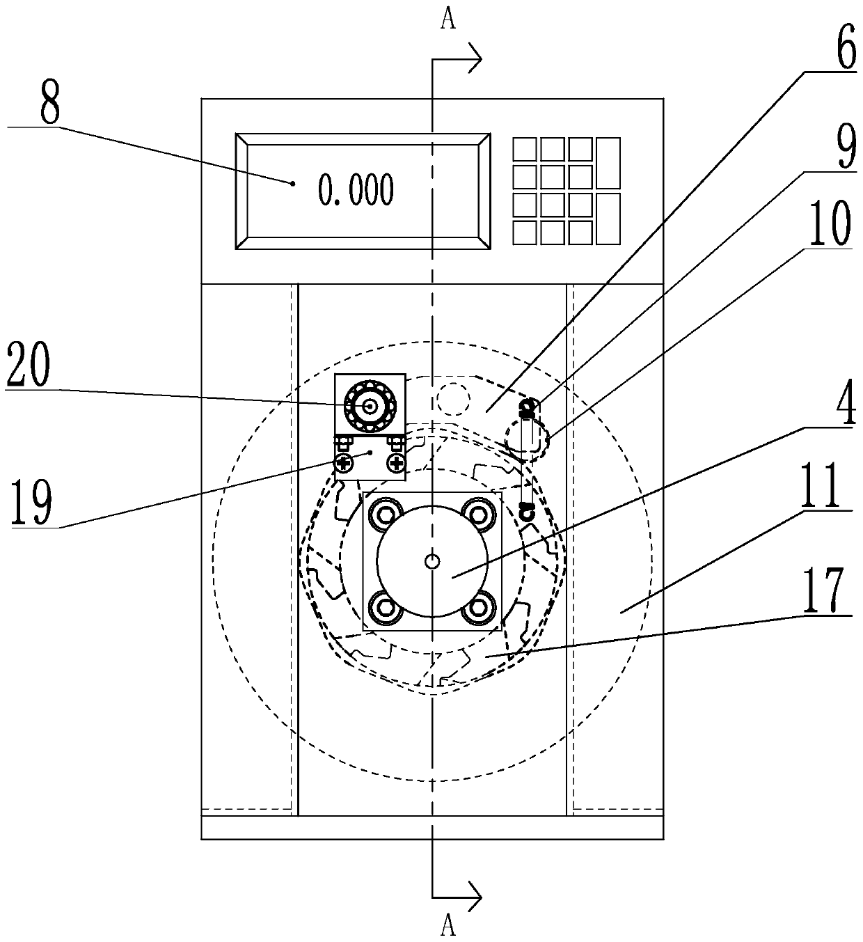
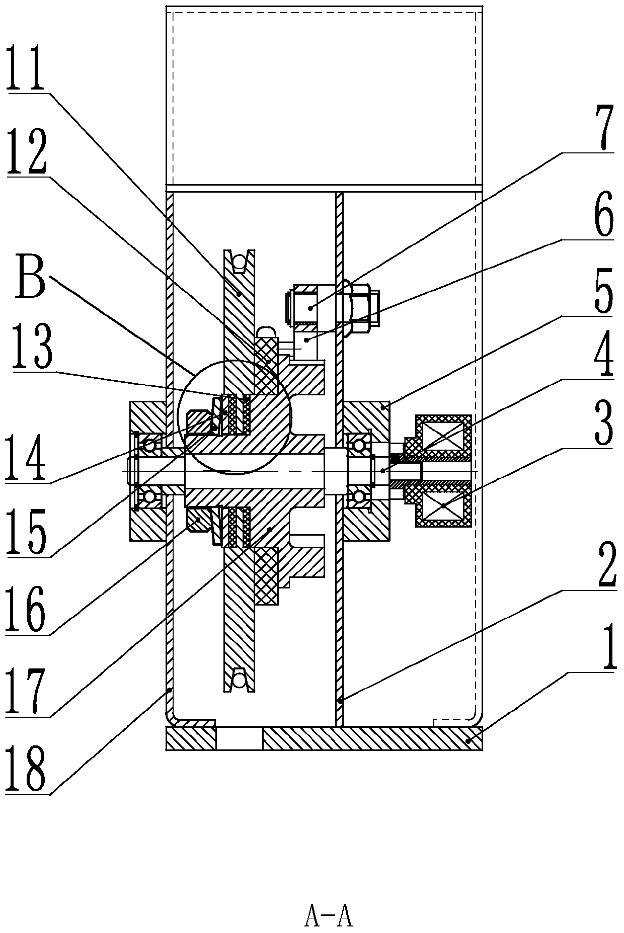
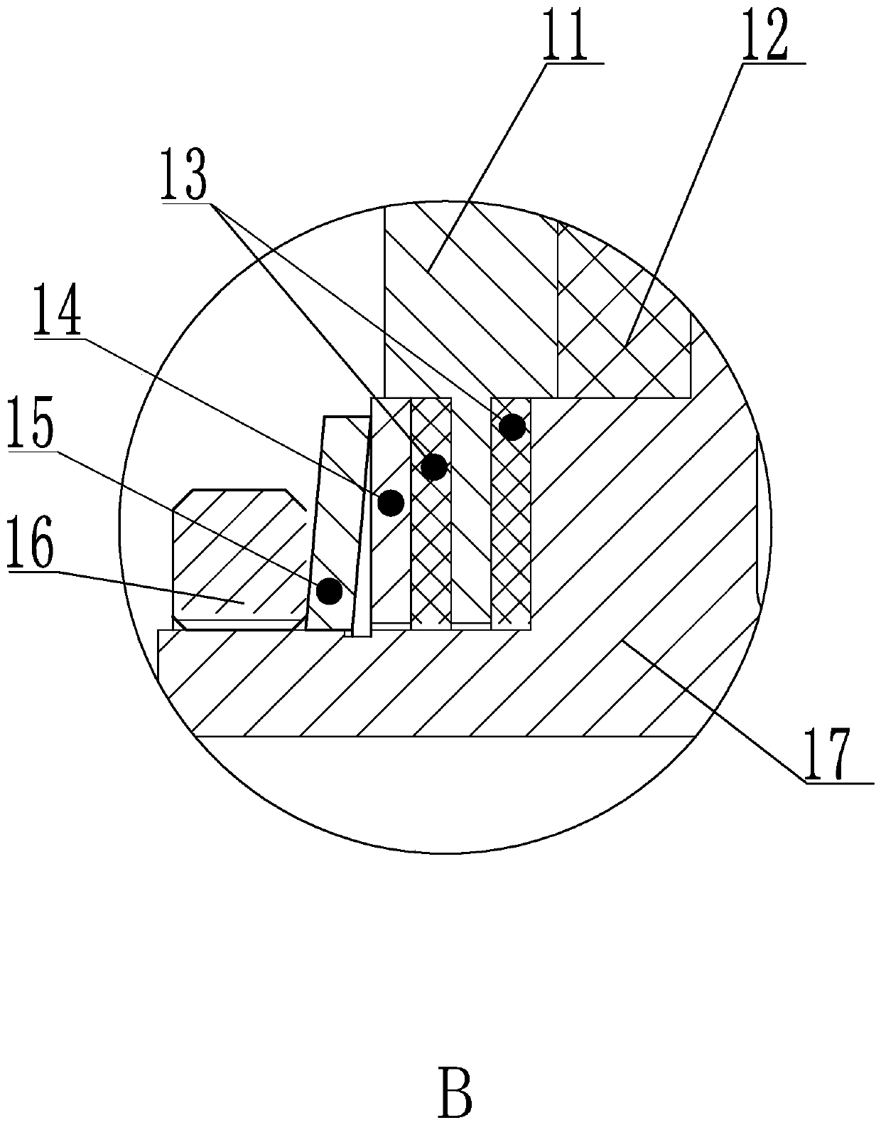
[0030] refer to Figure 1 to Figure 4 The embodiment of the elevator overspeed governor of the present invention will be further described.

[0031] A speed governor for an elevator, comprising a base plate 1 and a frame, the frame comprising a left bracket 18 and a right bracket 2, a sheave shaft 4 is arranged between the left bracket 18 and the right bracket 2, and a sheave shaft 4 is arranged on the sheave shaft 4 There is a brake wheel 17, which is an interference fit between the brake wheel 17 and the sheave shaft 4, and the brake wheel 17 is provided with a round platform facing the left bracket 18 side, and a rope wheel 11 is sleeved on the said round platform, and the rope wheel 11 and the brake wheel 17 are separately arranged, and the friction plate 13 that squeezes the sheave 11 is also arranged on the side of the corresponding sheave 11 on the said round platform, and the friction plate 13 is provided with two pieces, and the two friction plates 13 are respectively...


PUM


Abstract

The invention discloses an elevator speed limiter. The elevator speed limiter comprises a mounting bottom plate and racks, wherein a rope sheave shaft is arranged on the racks; a brake wheel is arranged on the rope heave shaft; one side of the brake wheel is provided with a circular truncated cone; a rope sheave sleeves the circular truncated cone; the rope sheave and the brake wheel are arranged in a split mode; friction plates for extruding the rope sheave are further arranged on the side surface, corresponding to the rope sheave, of the circular truncated cone; the two friction plates are respectively positioned at the two sides of the rope sheave; the end part of the circular truncated cone is provided with outer threads; a nut matched with the outer threads is further arranged on the circular truncated cone; an extrusion spring and a brake plate are further arranged on the circular truncated cone; the brake plate clings to the friction plate close to one side of the nut; and the extrusion spring is positioned between the nut and the brake plate. While operating at an overspeed, the rope sheave does not stop motion immediately, but speeds down to slowly rotate, so that a steel wire rope is always kept to synchronously move with the rope sheave, and the steel wire rope and the rope sheave do not have sliding friction, and therefore, the steel wire rope is prevented from being worn severely.

Description

technical field [0001] The invention belongs to the field of overspeed governors, and more specifically relates to an elevator overspeed governor. Background technique [0002] The elevator speed limiter is one of the safety control components in the elevator safety protection system. When the elevator is running for any reason, the car may overspeed or even fall, and all other safety protection devices do not work. live. [0003] The Chinese patent with application number 200420005455.4 discloses a two-way elevator overspeed governor, which includes a sheave, one side of the sheave has a brake disc, and the outer circle of the brake disc is surrounded by a plurality of brake grooves and a plurality of brake discs. The raised arc surface, the sheave is installed on the sheave shaft, and the sheave shaft is rotatably installed in the middle of the frame, the upper part of the frame can swing with a pendulum block, and the bottom of one end of the pendulum block can be rotat...

Claims


Application Information

Patent Timeline
Patent Type & Authority Patents(China)
IPC IPC(8): B66B5/04B66B5/18B66B3/00
CPCB66B3/002B66B5/044B66B5/18
Inventor 刘亚宁郑勇华
Owner HANGZHOU KANGTEER ELEVATOR COMPONENTS CO LTD
Why Eureka
Try Eureka