Yarn conveying lubrication device

A lubricating device and yarn technology, applied in textiles, papermaking, knitting, etc., can solve the problems that cannot meet the needs of production, the yarn is prone to breakage and burrs, and it is difficult to achieve soft, smooth and comfortable wearing. Achieve the effect of improving efficiency and quality, and simple structure

Active Publication Date: 2016-05-11
JIAXING TUHUANG CASHMERE CO LTD
View PDF7 Cites 8 Cited by
  • Summary
  • Abstract
  • Description
  • Claims
  • Application Information

AI Technical Summary

Problems solved by technology

[0002] Because of its good moisture absorption and air permeability, soft and comfortable to wear, and good warmth retention, the fabric has been widely used in our daily life, and the fabric has good dyeing performance, bright color, complete color spectrum, and strong alkali resistance. Heat and light resistance, especially warp-knitted fabrics, have good elongation and stretchability, and good dimensional stability. Need, it is necessary to use the winding device to wind each small yarn bobbin into a relatively large yarn bobbin, and then place the larger yarn bobbin on the warp knitting machine, so that the service life of the yarn bobbin is improved, ensuring that the warp knitting machine weaves In the process of winding a small yarn bobbin into a large yarn bobbin, the yarn needs to be conveyed. The traditional yarn conveying device cannot conveniently add yarn lubrication during the yarn conveying process. oil, so that the yarn is prone to breakage and burrs, and the fabric made of this yarn is also rough, and it is difficult to achieve soft, smooth and comfortable wearing effects, which cannot meet the needs of production

Method used


Image

  • Yarn conveying lubrication device
  • Yarn conveying lubrication device
  • Yarn conveying lubrication device

Examples


Embodiment Construction

[0011] In order to further describe the present invention, a specific implementation of a yarn conveying lubricating device will be further described below in conjunction with the accompanying drawings. The following examples are explanations of the present invention and the present invention is not limited to the following examples.

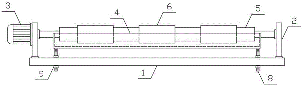
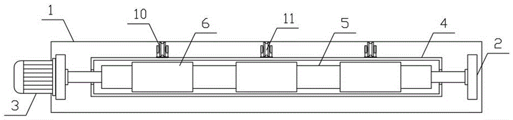
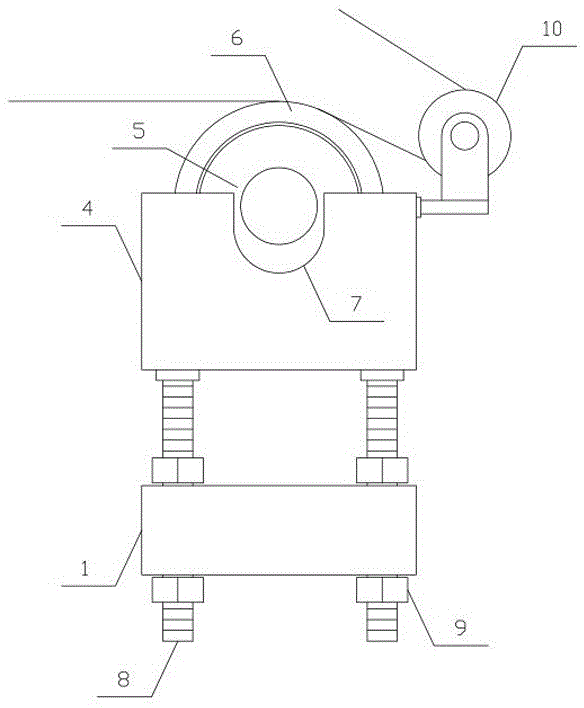
[0012] like figure 1 , figure 2 As shown, a yarn conveying lubricating device of the present invention includes a fixed bracket 1, a lubricating bracket 2, a lubricating motor 3 and an oil storage tank 4, the lubricating bracket 2 is arranged vertically and symmetrically on both sides above the fixing bracket 1, and the lubricating motor 3 is arranged horizontally On one side of the lubricating bracket 2, a lubricating roller 5 is horizontally connected to the lubricating bracket 2, and a plurality of lubricating rubber sleeves 6 are evenly arranged on the outer side of the lubricating roller 5. The oil storage tank 4 of the present invention i...


PUM


Abstract

The invention discloses a yarn conveying lubrication device and belongs to the field of textile processing machinery and equipment. The device comprises a fixing bracket, lubrication brackets, lubrication motors and an oil storage tank, wherein the lubrication brackets are vertically and symmetrically arranged on the two sides of the upper part of the fixing bracket; each lubrication motor is horizontally arranged on one side of each lubrication bracket; a lubrication roller is horizontally and rotationally connected to the lubrication bracket; a plurality of lubrication rubber sleeves are uniformly arranged on the outer side of the lubrication roller in sequence; the oil storage tank is horizontally arranged on the lower side of the lubrication roller; clamping grooves matched with the lubrication rollers are formed in the two sides of the oil storage tank respectively; two adjustment screw rods are vertically and uniformly arranged on the two sides of the lower part of the oil storage tank respectively and penetrate through the fixing bracket vertically and downwards; adjustment nuts are in threaded connection with the adjustment screw rods on the upper and lower sides of the fixing bracket; and a plurality of yarn guide wheels corresponding to the lubrication rubber sleeves are vertically and rotationally connected to one side of the oil storage tank. The device is simple in structure and can quickly and efficiently lubricate yarns in a conveying process to meet the needs of production and use.

Description

technical field [0001] The invention belongs to the field of textile processing machinery and equipment, in particular to a yarn transmission lubricating device. Background technique [0002] Because of its good moisture absorption and air permeability, soft and comfortable to wear, and good warmth retention, the fabric has been widely used in our daily life, and the fabric has good dyeing performance, bright color, complete color spectrum, and strong alkali resistance. Heat and light resistance, especially warp-knitted fabrics, have good elongation and stretchability, and good dimensional stability. Need, it is necessary to use the winding device to wind each small yarn bobbin into a relatively large yarn bobbin, and then place the larger yarn bobbin on the warp knitting machine, so that the service life of the yarn bobbin is improved, ensuring that the warp knitting machine weaves In the process of winding a small yarn bobbin into a large yarn bobbin, the yarn needs to be...

Claims


Application Information

Patent Timeline
Patent Type & Authority Applications(China)
IPC IPC(8): D04B35/24
CPCD04B35/24
Inventor 顾晓青
Owner JIAXING TUHUANG CASHMERE CO LTD
Why Eureka
Try Eureka