Passive protective net and installation method thereof
A passive protection and control device technology, applied in protective equipment, excavation, construction, etc., can solve problems such as difficult to find, unfavorable maintenance and maintenance, and achieve the effects of environmental protection, artificial greening, and detection of danger
- Summary
- Abstract
- Description
- Claims
- Application Information
AI Technical Summary
Problems solved by technology
Method used
Image

Examples
Embodiment 1
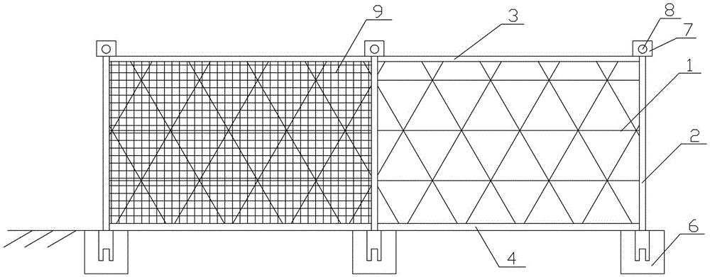
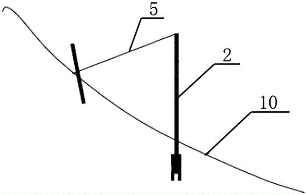
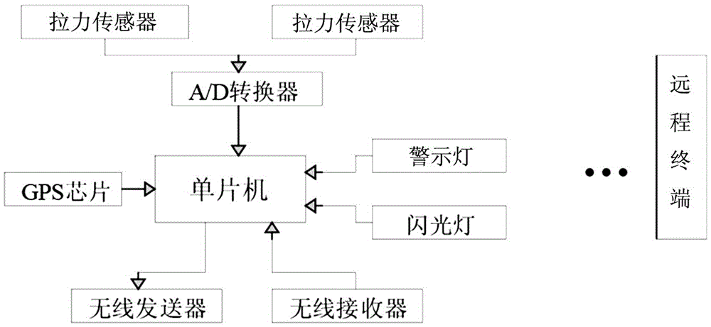
[0028] Embodiment 1: A kind of passive protective net, comprises steel wire netting, the steel column of fixing steel wire netting, upper support rope, lower support rope and pull-up anchor rope, and the bottom of steel column is fixedly installed on the base by connecting screw rod, and upper support rope 1. The lower support rope fixes the steel wire rope net and the steel column together, and pulls up the anchor rope to tighten and fix the top of the steel column. The passive protective net also includes a warning component, which includes a tension sensor set on the wire rope net, upper support rope or pull-up anchor rope, a control device set on the top of the steel column, a warning light and a buzzer; the control device includes GPS positioning modules, wireless transmission modules, control modules, and power modules that provide power for each module; the tension sensor is connected to the control module through an A / D converter, and the warning lights and buzzers are ...
PUM
 Abstract
Description
Claims
Application Information
PatSnap Eureka turns technology decisions into work you can execute. Powered by our Innovation Knowledge Graph, it runs expert workflows across engineering, life sciences, materials and intellectual property. Get your review-ready output in minutes.


